Konica Minolta ProJet 160 Cube3 User Guide - Page 86
NOTE: Use a 1°5 mm Allen wrench that is included with the printer°
 |
View all Konica Minolta ProJet 160 manuals
Add to My Manuals
Save this manual to your list of manuals |
Page 86 highlights
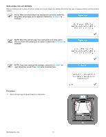
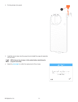
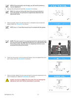
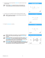
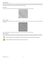
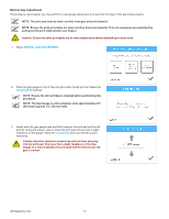
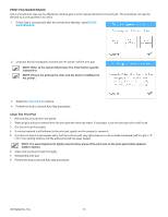
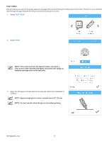
NOTE: If the print pad is out of range, you will need to perform a manual adjustment. 4. Remove the print pad and select the checkmark to continue. NOTE: To remove it, lift up the front of the print pad and pull it out of the printer. The print pad is magnetically attached to the adjustment knobs. 5. When prompted, loosen the lock screw that is indicated on the touchscreen display. Select the checkmark to continue. NOTE: Use a 1.5 mm Allen wrench that is included with the printer. NOTE: The lock screw (1) is located just below the adjustment knob (2). The lock screw for adjustment knob B can be accessed from the front of the printer. The lock screw for adjustment knob A can be 2 accessed from behind the printer. 1 6. Follow the instructions on the touchscreen display. Once the adjustments have been made, select the checkmark to continue. 7. When prompted, tighten the lock screw enough to ensure the adjustment knob does not easily turn. Select the checkmark to continue. Caution: Do not over-tighten the lock screw. This can damage the adjustment knob and void the manufacturer's warranty. 3D Systems, Inc. 82
-
 1
1 -
2
-
3
-
4
-
5
-
6
-
7
-
8
-
9
-
10
-
11
-
12
-
13
-
14
-
15
-
16
-
17
-
18
-
19
-
20
-
21
-
22
-
23
-
24
-
25
-
26
-
27
-
28
-
29
-
30
-
31
-
32
-
33
-
34
-
35
-
36
-
37
-
38
-
39
-
40
-
41
-
42
-
43
-
44
-
45
-
46
-
47
-
48
-
49
-
50
-
51
-
52
-
53
-
54
-
55
-
56
-
57
-
58
-
59
-
60
-
61
-
62
-
63
-
64
-
65
-
66
-
67
-
68
-
69
-
70
-
71
-
72
-
73
-
74
-
75
-
76
-
77
-
78
-
79
-
80
-
 81
81 -
 82
82 -
 83
83 -
 84
84 -
 85
85 -
 86
86 -
 87
87 -
 88
88 -
 89
89 -
 90
90 -
 91
91 -
92
-
93
-
94
-
95
-
96
-
97
-
98
-
99
-
100
-
101
-
102
 |
 |