Sharp UX-4000M Service Manual
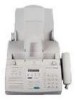
Sharp UX-4000M - UX 4000 B/W Laser Printer Manual
 |
View all Sharp UX-4000M manuals
Add to My Manuals
Save this manual to your list of manuals |
Sharp UX-4000M manual content summary:
- Sharp UX-4000M | Service Manual - Page 1
at the time of servicing. 1) When a problem in the laser optical unit has occurred, the whole optical unit must be exchanged as a unit, not an individual part. 2) Do not look into the machine with the main switch turned on after removing the toner/developer unit and drum cartridge. 3) Do not look - Sharp UX-4000M | Service Manual - Page 2
Troubleshooting 1-12 [7] Quick reference guide 1-14 CHAPTER 2. ADJUSTMENTS [1] Adjustments 2-1 [2] Diagnostics and service soft switches 2-4 [3] Troubleshooting TEL/LIU and Hook SW PWB 5-21 [4] Circuit description of power supply PWB 5-23 [5] Circuit description of CIS UNIT 5-24 CHAPTER 6. - Sharp UX-4000M | Service Manual - Page 3
* Approx. 6 seconds Toner cartridge yield (4% page coverage, letter paper) Initial starter cartridge (included with fax machine): Approx. 1,875 pages Replacement cartridge (UX-400ND): Approx. 3,750 pages Drum cartridge yield Initial starter cartridge (included with fax machine): 20,000 pages - Sharp UX-4000M | Service Manual - Page 4
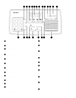
. 4 TONER EMPTY indicator This blinks when the toner cartridge nears empty and lights steadily when the toner cartridge needs replacement press this key to print out the Help List, a quick reference guide to the operation of your fax machine. 20 HOLD/SEARCH key Press this key search for an auto-dial - Sharp UX-4000M | Service Manual - Page 5
sizes, only one sheet can be fed into the machine at a time. Insert next page into feeder as Paper of fine quality/bond paper/ Kent paper UX-4000MU FO-2950MU/C 4. Cautions on Transmitting Documents : max. 20 sheets Special size: single sheet only (manual feed) NOTES: • • If you need to send - Sharp UX-4000M | Service Manual - Page 6
a toner cartridge and a drum cartridge. The drum cartridge comes pre-installed, and the toner cartridge must be installed. The starter toner cartridge included with your fax can print approximately 1,875 letter-size pages st 4% page coverage When replacing the toner cartridge, use a Sharp UX-400ND - Sharp UX-4000M | Service Manual - Page 7
the following cartridge: Sharp UX-400DR drum cartridge 1 Grasp the print compartment cover at both sides as shown, and pull up to open the cover. • Caution! The fusing unit inside the print compartmt becomes very hot during operation. Do not touch the inside of the compartment or the paper guide on - Sharp UX-4000M | Service Manual - Page 8
or leave any pieces of paper in the machine 3 Grasp the tabs on the drum cartridge handle and gently pull the cartridge out of the machine. 7 Replace the toner cartridge and reset the drum counter. (Refer to Installing the Toner Cartridge .) 4. Connections 1 Connecting the Handset Connect the - Sharp UX-4000M | Service Manual - Page 9
any other kind of outlet. This will damage the machine and is not covered under the warranty. UX-4000MU FO-2950MU/C 2) Press 1 to select tone the original document support. • Make sure the front side of the support faces you (the support should curve slightly toward you). • Note: Your fax is set - Sharp UX-4000M | Service Manual - Page 10
UX-4000MU FO-2950MU/C 2) Connect the extension phone line to the TEL. SET jack. 4 5 Make sure the stack of paper is aligned against the right paper quide, and then gently move the left paper guide to the 8 1/2 position for letter or legal paper, or the A4 position for A4 paper. 2 Fan the paper, - Sharp UX-4000M | Service Manual - Page 11
1 Open the operation panel by grasping the panel release and pulling up. UX-4000MU FO-2950MU/C 3 Close the operation panel, making sure it clicks into paper 1 If most of the jammed page is protruding from the back of the fax, pull the paper release lever toward you and try pulling the page out. 2 - Sharp UX-4000M | Service Manual - Page 12
surface. 8 Replace the drum cartridge. • To insert the cartridge, align the guides on the cartridge with the runners on the sides of the compartment. 5 Grasp the tabs on the drum cartridge handle and gently pull the cartridge out of the machine. 9 Replace the toner cartridge and close the print - Sharp UX-4000M | Service Manual - Page 13
rollers UX-4000MU FO-2950MU/C 2 Grasp the finger hold on the toner cartridge toner cartridge out of the compartment. • Place the toner cartridge on a sheet of paper on a level surface. White backplate 3 Grasp the tabs on the drum cartridge handle and gently pull the cartridge out of the machine - Sharp UX-4000M | Service Manual - Page 14
UX-4000MU FO-2950MU/C 6 Replace the drum cartridge. • To insert the cartridge, align the guides on the cartridge with the runners on the sides of the compartment. [6] Troubleshooting 1. Using the RESET key If the fax machine stops responding when you press any of the operation panel keys, you must - Sharp UX-4000M | Service Manual - Page 15
indicates the problem. The fax will print out automatically when the problem is resolved ) UX-4000MU FO-2950MU/C OFF HOOK ON HOOK DIAL OUT OF PAPER PAPER JAMMED SEND READY REPLACE TONER SEARCH and the fax machine is waiting for you to begin faxing or copying. The toner cartridge must be replaced - Sharp UX-4000M | Service Manual - Page 16
FAX mode: The fax machine automatically answers on four rings and receives the incoming document. TEL mode: Beep START RECEIVING A.M. mode: Select this mode when an answering machine is connected to the fax and the answering machine is turned on. UX-4000MU FO-2950MU/C [7] Quick reference guide - Sharp UX-4000M | Service Manual - Page 17
power supply unit in the machine. 2. Set the recording paper and document. 3. When the document is loaded, power is supplied to (effective value meter). MC DRUM + MC output voltage check - • Capacitor: 1000pF/3KV (VCKYQY3FB102K) • Diode: SHV-03 (VHDSHV03///-1) UX-4000MU FO-2950MU/C Output +5V - Sharp UX-4000M | Service Manual - Page 18
UX-4000MU FO-2950MU/C 2 DC bias output voltage adjustment Adjust VR2 so that the output voltage is -310V ±5V For measurement, use the high voltage tester (effective value me- ter). - DC-Bias Output voltage check + DRUM DC-Bias VR1 (MC output voltage adjustment volume) - BC-Bias Output voltage - Sharp UX-4000M | Service Manual - Page 19
MODE (Soft Switch No. SW2 DATA No. 1) Use this to set the fax machine to the type of telephone line you are on. • The factory setting is : PULSE SELECTED (step 4) End, using the "STOP" key. KEY: STOP UX-4000MU FO-2950MU/C CNRTH CNFUSE F100 CNM1 IC6 CNPRT CNPN CNCIS CNLIUA CNSP CNLIUB Control - Sharp UX-4000M | Service Manual - Page 20
UX-4000MU FO-2950MU/C [2] Diagnostics and service soft switches 1. Operating procedure Two kinds of diagnoses are supported. 1-1. Fax diagnosis This diagnosis is concerned with the main body of fax which is used for production and service support. Entering the diagnostic mode Press FUNC 9 8 7 , - Sharp UX-4000M | Service Manual - Page 21
pattern is: on for 0.25 seconds and then off for 0.25 seconds. UX-4000MU FO-2950MU/C 4) Panel key test This is used to check whether Signal send mode This mode is used to send various signals to the circuit during FAX communication. Every push of START key sends a signal in the following sequence. - Sharp UX-4000M | Service Manual - Page 22
UX- document. (After entering this mode, when a document is placed in the machine and the START key is pressed, the operation will start.0) After this 11) TEL. number set The function is used to simplify the registration of FAX/TEL No. during 1aging. The diagnosis mode is activated. If anything is - Sharp UX-4000M | Service Manual - Page 23
MACH I NE = 0 0 0 1 2 3 DRUM L I F E = 0 0 0 1 2 3 L I FE1=000123 key L I FE2=000123 L I FE3=000123 FEEDER L F= 0 0 0 1 2 3 TONER L F = 0 0 0 1 2 3 The counter should be reset or cleared in addition to the ordinary memory clear. UX-4000MU FO-2950MU/C Rapid key 07: Life all clear The mode is - Sharp UX-4000M | Service Manual - Page 24
UX-4000MU FO-2950MU/C Rapid key 10: Life clear mode The mode is used can be selected with the "#" and " " keys. MACH I NE L F C L EAR DRUM L I F E C L E AR # key L I FE1 CLEAR key L I FE2 CLEAR L I FE3 CLEAR FEEDER LF CLEAR TONER L I F E C L EAR 2 1 In the state of , select the counter value - Sharp UX-4000M | Service Manual - Page 25
mode, make the following key entries in sequence. Press FUNCTION 9 8 7 START 0 1 START UX-4000MU FO-2950MU/C SFT S W 1 = 0 0 0 0 0 0 0 0 SFT S W 1 = 1 0 0 0 0 0 0 0 SFT S W 1 = 1 0 0 0 0 0 0 0 SFT S W 1 = 1 0 0 0 0 0 0 0 SFT S W 1 = 1 0 0 0 0 0 0 0 SFT S W 2 = 0 0 0 0 0 0 0 0 S F T S W 53 - Sharp UX-4000M | Service Manual - Page 26
UX-4000MU FO-2950MU/C 4. Soft switch description • Soft switch SW DATA NO. NO. ITEM 1 Recall interval 2 3 4 SW1 5 Recall times 6 7 8 1 Dial mode 2 Reception mode 3 ECM mode 4 CNG detection in standby mode SW2 5 Polling security 6 Automatic cover sheet 7 Junk fax function in manual - Sharp UX-4000M | Service Manual - Page 27
timer (Distinctive ring setting off only) Distinctive ringing setting Factory setting : OFF UX-4000MU FO-2950MU/C Switch setting and function 1 0 Initial setting Remarks No Yes 0 Yes No (depends on remote machine) 0 0 0 V.17 V. 29 V. 27ter 14400 12000 9600 7200 9600 7200 4800 2400 - Sharp UX-4000M | Service Manual - Page 28
UX-4000MU FO-2950MU/C SW DATA NO. NO. ITEM End buzzer 1 2 3 Communication error treatment in RTN sending mode (reception) SW11 4 CNG transmission after auto dialing 5 Error criterion 6 Pulse to tone change by key 7 CNG transmission in manual transmission 8 Reserved 1 DTMF signal - Sharp UX-4000M | Service Manual - Page 29
UX-4000MU FO-2950MU/C SW DATA NO. NO. ITEM 1 2 3 4 SW16 5 6 7 8 1 2 3 4 SW17 5 6 7 8 1 2 0 1 Off High Middle Low 0 0 1 1 0 1 0 1 Off High Low Low 0 0 1 1 0 1 0 1 FAX No Cannot change Yes Automatic printout Off Fine No. 1 No. 2 No. 3 No. 4 Normal 0 0 Normal 0 0 PC Yes - Sharp UX-4000M | Service Manual - Page 30
UX-4000MU FO-2950MU/C SW DATA NO. NO. 1 2 3 4 SW21 5 6 7 8 1 2 3 4 SW22 5 6 7 8 1 2 3 SW23 4 5 6 7 8 1 2 3 SW24 4 5 6 7 8 1 2 3 4 SW25 5 6 6pulses No. 7 0 0 1 No. 8 0 1 0 TAD connect Yes No Fax switching when A.M. full Yes No Selection time of quiet detection 30sec 40sec 50sec No. 3 - Sharp UX-4000M | Service Manual - Page 31
7 Reserved 8 Reserved Switch setting and function 1 0 Binary input 8421 No. = 1 2 3 4 0 1 0 0 (4sec) Binary input No. = 8421 5678 0 1 0 1 (5sec) UX-4000MU FO-2950MU/C Initial setting 0 1 0 0 0 1 0 1 0 0 0 0 0 0 0 0 0 0 0 0 0 0 0 0 0 0 0 0 0 0 0 0 0 0 0 0 0 0 0 0 Remarks OPTION 2 - 15 - Sharp UX-4000M | Service Manual - Page 32
UX-4000MU FO-2950MU/C SW DATA NO. NO. 1 2 3 4 SW32 5 6 7 8 1 2 3 4 SW33 5 6 7 8 1 2 3 4 SW34 5 6 7 8 1 2 3 4 SW35 5 6 7 8 1 2 3 4 SW36 5 6 7 8 1 2 3 4 SW37 5 6 7 8 1 2 3 4 SW38 5 6 7 8 Reserved Reserved Reserved Reserved Reserved Reserved Reserved Reserved Reserved Reserved Reserved - Sharp UX-4000M | Service Manual - Page 33
8 Reserved 1 Reserved 2 Reserved 3 Reserved 4 Reserved SW44 5 Reserved 6 Reserved 7 Reserved 8 Reserved ITEM Switch setting and function 1 0 UX-4000MU FO-2950MU/C Initial setting 0 0 0 0 0 0 0 0 0 0 0 0 0 0 0 0 0 0 0 0 0 0 0 0 0 0 0 0 0 0 0 0 0 0 0 0 0 0 0 0 0 0 0 0 0 0 0 0 Remarks 2 - 17 - Sharp UX-4000M | Service Manual - Page 34
UX-4000MU FO-2950MU/C SW DATA NO. NO. 1 Reserved 2 Reserved 3 Reserved 4 Reserved SW45 5 Reserved 6 Reserved 7 Reserved 8 Reserved 1 Reserved 2 Reserved 3 Reserved 4 Reserved SW46 5 Reserved 6 Reserved 7 Reserved 8 Reserved 1 - Sharp UX-4000M | Service Manual - Page 35
Reserved Reserved Reserved Reserved Reserved Reserved Reserved Reserved Reserved Reserved Reserved Reserved Reserved Reserved Reserved Reserved Reserved ITEM Switch setting and function 1 0 UX-4000MU FO-2950MU/C Initial setting 0 0 0 0 0 0 0 0 0 0 0 1 1 0 1 0 0 0 1 0 0 0 1 1 Remarks 2 - 19 - Sharp UX-4000M | Service Manual - Page 36
UX-4000MU FO-2950MU/C • Soft switch function description SW1 No. 1 ~ No. 4 Recall fax function in manual reception It is set whether JUNK-FAX is functioned in the manual receiving mode or not. SW2 No. 8 Anti junk fax function This function is used to receive data from a specific remote machine - Sharp UX-4000M | Service Manual - Page 37
contains the sender's phone number registered in the machine. If this switch is set to "1", no problem, if set to 1. UX-4000MU FO-2950MU/C SW7 No. 5 EOL detect timer 25 seconds or 13 seconds are selected for the detection timer of EOL (end of line). This is effective against communication trouble - Sharp UX-4000M | Service Manual - Page 38
UX-4000MU FO-2950MU/C SW10 No. 3, No. 4 CI off detection timer (Distinctive ring dial mode to the tone dial mode. key from the SW11 No. 7 CNG transmission in manual transmission CNG signal sending ON/OFF in case of manual transmission is set. SW11 No. 8 Reserved Set to "0". SW12 No. 1 ~ No. - Sharp UX-4000M | Service Manual - Page 39
however, the fine mode is automatically selected unless the Resolution key is manually set to another mode. SW19 No. 1 , No. 2 Density adjustment in the half tone. Setting procedures are the same as SW19 No. 1, No. 2. UX-4000MU FO-2950MU/C SW19 No. 5, No. 6 Reserved Set to "0". SW19 No. 7 - Sharp UX-4000M | Service Manual - Page 40
UX-4000MU FO-2950MU/C SW25 No. 1 Busy tone detection ON/OFF time (Shorter a no sound status is detected for a certain period of time, the machine judges it as s transmission from a facsimile machine and automatically switches to the FAX mode. SW27 No. 5 ~ No. 8 Quiet detect start timing Inserts - Sharp UX-4000M | Service Manual - Page 41
Set to "0". SW53 No. 1, No. 2 Reserved Set to "0". SW53 No. 3 Reserved Set to "1". SW53 No. 4 ~ No. 6 Reserved Set to "0". SW53 No. 7, No. 8 Reserved Set to "1". UX-4000MU FO-2950MU/C 2 - 25 - Sharp UX-4000M | Service Manual - Page 42
UX-4000MU FO-2950MU/C [3] Troubleshooting 1. Fax troubleshooting Refer to the following actions to troubleshoot any of the problems mentioned in 1-4. [1] A communication error occurs. [2] Image distortion produced. [3] Unable to do overseas communication. [4] Communication speed slow due to FALLBACK - Sharp UX-4000M | Service Manual - Page 43
signal frame Error Condition (Receiver side) Cannot recognize bit stream after flag UX-4000MU FO-2950MU/C 1 NSF, DIS 2 CFR 3 FTT 4 MCF 11 − Error occurred after or during inquiry from the remote (transmitting) machine as to whether reception is possible or not. 12 − Error occurred - Sharp UX-4000M | Service Manual - Page 44
UX in the hopper), the next document is supplied and fed nearly when the last document face down in the hopper. • Adjust the document guides to the document width. • Align the top edge manually. Documents corresponding to a paper weight heavier than 90kg and lighter than 135kg are acceptable for manual - Sharp UX-4000M | Service Manual - Page 45
4. Paper Path Print Exit UX-4000MU FO-2950MU/C Document Exit 5. Components Layout Fig. 4 1 2 3 4 5 6 7 separation sheet No. PARTS NAME 21 PIN sensor 22 Toner supply roller 23 Developing roller 24 Transfer charger roller 25 Photoconductor drum 26 Discharge brush 27 Pressure roller 28 Heat roller - Sharp UX-4000M | Service Manual - Page 46
UX-4000MU FO-2950MU/C 6. Switch, Sensor Layout 8 1 4 2 3 6 7 5 Fig. 6 No. PARTS NAME 1 PE sensor (Paper Empty sensor) 2 Front cover open detector 3 POUT sensor (Paper OUT sensor) 4 PIN (Paper In) sensor 5 Temperature fuse 187˚C 6 Temperature fuse 132˚C 7 Thermistor 8 Toner the drum are started - Sharp UX-4000M | Service Manual - Page 47
cleaning. 7-2. System diagram Scanning mirror Laser beam Laser beam generator No.1 ~ No.3 Mirrors UX-4000MU FO-2950MU/C DC-850V AC600V(P-P) Main charger brush Developing roller Toner Photoconductor drum DC-250V DC+500V Separation electrode Transfer roller Paper DC+3500V AC600V(P-P) DC - Sharp UX-4000M | Service Manual - Page 48
131 MCON 5 MCON 12 Q7 Driver IC1 TC-BIAS ON 129 TC/Bias ON 3 14 Q3 Q9 Q8 +24VP T2 Trans +24VP Q5 T1 Trans Q6 Charger roller MC OPC DRUM Separation electrode TC DC 100V Bias Transfer roller Doctor CPU (SH7041) 115 PW MSIN Q4 Developing roller Supply roiier Fig. 8 7-3. Image forming - Sharp UX-4000M | Service Manual - Page 49
1 10 4 9 5 8 7 6 1 Developing roller 2 Doctor 3 Toner stirring plate 4 Toner supply roller Fig. 10 5 Toner seal 9 Discharge brush 6 F Transfer roller Main charger 7 Separation brush G Toner seal electrode 8 OPC drum (1) OPC drum unit The OPC drum is charged and latent electrostatic - Sharp UX-4000M | Service Manual - Page 50
UX-4000MU FO-2950MU/C 7-5. Image forming operation STEP 1 (Cleaning, Charging): Residual toner the OPC drum is stirred and negative charges are scattered evenly on the OPC drum. (The OPC drum surface is evenly charged.) The main charger is a rotating brush roller. The main charger removes residual - Sharp UX-4000M | Service Manual - Page 51
to laser beam) Grounding sheet DC -310V OPC drum Aluminum layer (Drum base) CGL CTL Paper Aluminum layer (Drum base) CGL CTL Fig. 14 Toner is transported to the scraper area by the toner supply roller and the developing roller. The quantity of toner to be transported to the doctor section is - Sharp UX-4000M | Service Manual - Page 52
UX-4000MU FO-2950MU/C STEP 5 (Paper separation): The paper is separated from the OPC drum. STEP 6 (Discharge): The drum surface is discharged to facilitate cleaning of the drum surface. (The remaining toner is easily collected by the main charger roller. Aluminum layer (Drum base) CGL CTL Main - Sharp UX-4000M | Service Manual - Page 53
of OPC drum surface potential by print operation UX-4000MU FO-2950MU/C (2) OPC drum surface potential and developing bias voltage in development OPC surface potential (-V) OPC drum surface potential (-V) -850V Laser beam Dark area potential -250V Toner attachment potential Developing - Sharp UX-4000M | Service Manual - Page 54
UX supply PWB unit 5. Feed guide unit, Scanner bracket 6. Document guide lower, Scanner unit 7. Panel unit, Document guide MC (High voltage terminal: Photocon- ductor drum main charger) 31. High voltage terminal required for disassmbly and assembly of this machine. As general tools, screwdrivers (+) - Sharp UX-4000M | Service Manual - Page 55
0238FCZZ) to the fusing clutch gear teeth and the inside. UX-4000MU FO-2950MU/C 5 Apply Floil G-484 (UKOG-0238FCZZ) to the drum lock lever. Fig. 2 3 Apply Floil G-484 ( the imaging cartridge and the drum cartridge before disassembly. e. The parts which are not described in the parts guide must not - Sharp UX-4000M | Service Manual - Page 56
UX-4000MU FO-2950MU/C 1. Panel unit 1 Remove screw, and remove ROM cover. (Hook x 5) 2 Remove three screws. 3 Remove screw. 4 Remove four cables, and remove Panel unit. 5 Remove - Sharp UX-4000M | Service Manual - Page 57
two connectors, and remove Control PWB unit and TEL/ 4 LIU PWB unit. Remove five screws, and remove printer unit. 1 1 UX-4000MU FO-2950MU/C 4. Printer PWB unit, Power supply PWB unit 1 Remove four screws, and remove Printer unit. 2 Remove four cables. 3 Remove five screws. 4 Remove fan motor cable - Sharp UX-4000M | Service Manual - Page 58
UX-4000MU FO-2950MU/C 5. Feed guide unit, Scanner bracket 1 Remove two screws, and remove Feed guide unit. (Hook x 7) 2 Remove two screws. 3 Remove three cables. 4 Remove two screws, and remove Scanner bracket. 5 Remove two screws. HOOK Shading plate 5 Feed guide unit HOOK 5 HOOK 1 HOOK 2 3 - Sharp UX-4000M | Service Manual - Page 59
upper unit 1 Remove two screws, and remove document guide upper unit. 1 Document guide upper unit 8. Drive unit 1 Remove two screws, and remove Drive unit. 2 Remove two screws. UX-4000MU FO-2950MU/C 2 Transfer motor Radiation plate Drive frame Panel unit Fig. 13 Drive unit 1 Scanner frame - Sharp UX-4000M | Service Manual - Page 60
UX-4000MU FO-2950MU/C 9. Upper frame unit (optical frame unit) 1 Remove three drive gear A 4 Motor idle gear 3 Gear plate 1 Fusing clutch lever Fusing clutch gear B Fusing clutch spring Drum idle gear Fusing clutch gear A 2 6 Remove the arm of upper frame unit from the lower frame boss. - Sharp UX-4000M | Service Manual - Page 61
When attaching main motor, put the cable to the right side. Main motor 4 3 3 Fusing gear cover PU idle gears 2 1 3 Remove the tray lock lever. UX-4000MU FO-2950MU/C Tray lock lever 3 Fig. 19 The clearance between the clutch boss and the clutch gear must be 0.1(+0.02/-0.03)mm 4 Remove the - Sharp UX-4000M | Service Manual - Page 62
UX-4000MU FO-2950MU/C 12. Paper feed solenoid 1 Remove connector. 2 Remove lever release spring which is attached to sleeve release lever. 3 Remove one screw. 4 Slide paper - Sharp UX-4000M | Service Manual - Page 63
2 Pull out motor idle gear. 3 Remove fan belt from developer drive gear A. 4 Remove fan belt from between fan and fan cover. Developer drive gear A UX-4000MU FO-2950MU/C 17. Fusing unit 1 Remove connectors. 2 1 Release the protect of the cable connected to from the lower 3 frame. Remove two fixing - Sharp UX-4000M | Service Manual - Page 64
UX-4000MU FO-2950MU/C 19. Heat roller, heater lamp 1 Remove two screws. 2 Lift up the heat roller together with heater lamp, and slide it in the - Sharp UX-4000M | Service Manual - Page 65
installing direction of the ther- mistor. Attach so that the thermistor orange cover side is on the front side of the heat roller. Thermistor 1 Thermistor UX-4000MU FO-2950MU/C 23. Paper exit roller upper 1 Bend the shaft of paper exit roller upper A, and disengage it from the 2 Hook of fusing - Sharp UX-4000M | Service Manual - Page 66
UX-4000MU FO-2950MU/C 24. Transfer roller 1 Insert a screwdriver into the time, fusing clutch gear A and fusing clutch spring are also disassembled. 2 Pull out motor idle gear and remove drum idle gear. 3 Remove earth terminal fixing screw. 4 Slide the earth terminal in the direction of A and remove - Sharp UX-4000M | Service Manual - Page 67
Separation electrode Bent section UX-4000MU FO-2950MU/C 27. PIN actuator (Paper in detection lever direction and remove it from the lower frame. POUT actuator 1 Boss 5 Separation electrode Fig. 40 Note : Drum earth electrode so that it is on the terminal on the PWB unit as follows. Fig. 43 Note - Sharp UX-4000M | Service Manual - Page 68
UX-4000MU FO-2950MU/C 29. Separate plate ass'y 1 Insert a screwdriver (-) 2 Remove PU idle gears. Fig. 45 30. High voltage terminal DR-MC (High voltage terminal: Photoconductor drum main charger) 1 Remove high voltage terminal DR-MC. • Terminal cover is included. Cover High voltage terminal - Sharp UX-4000M | Service Manual - Page 69
5 Remove two screws. 6 Pull DV bias electrode toward you, and remove it from the lower frame. UX-4000MU FO-2950MU/C Optical section • Do not touch the mirror fixing screw in the optical section. If touched, the mirror bracket may be change, causing a - Sharp UX-4000M | Service Manual - Page 70
DRAM ONLY PC-PRINT CNPRT SENTRONICS CABLE PERSONAL COMPUTER FAN MOTOR CNFM CNPW HEATER LAMP CNHT POWER PWB PRINTER PWB CNPL CNTNR PICK UP SOLENOID TONER SENSOR CNMMT PAPER FEED MOTOR CNLSU LASER UNIT UX-4000MU FO-2950MU/C CHAPTER 4. DIAGRAMS [1] Block diagram - Sharp UX-4000M | Service Manual - Page 71
6 PRINTER MOTOR 4 LASER AUTO POWER SCANING MOTOR 5 CONTROL PWB 9 Beam Detector PWB 3 PC LSU UNIT TONER SENSOR 5 PICKUP SOLENOID 2 36 CNPL CNTNR CNLSU CNMMT CNMT CNPN UX-4000MU FO-2950MU/C CN101 CNPW SPEAKER CIS 2 7 CNCIS CONTROL PWB CNSP 12 FJ HANDSET CNLIUA CNLIUA - Sharp UX-4000M | Service Manual - Page 72
LSU UNIT TONER SENSOR PC 3 HLN 1L 2 N.C. 3N CN2 POWER SUPPLY CN1 CNPRT 1a POUT1b PWMSIN 2a PIN2b DOP3a TSEN LD1 8 LD2 9 LD3 10 P-CHK 11 TONER 12 PC IN USE 13 TEL LINE 14 FRTSNS N.C. 9 10 LD3 N.C. 10 11 P-CHK LD0 11 12 TONER LD1 12 13 PC IN USE LD2 13 14 TEL LINE LD3 - Sharp UX-4000M | Service Manual - Page 73
SUPPLY PWB PRINTER PWB LSU UNIT PICK UP SOLENOID PRINTER MOTOR TONER LCD display. UX-4000MU FO-2950MU manual and automatic. Depression of the START key in the off-hook mode in the case of manual modem interface of the 1 fax CPU(SH2) which is COPY key is pressed when the machine is in stand-by with a - Sharp UX-4000M | Service Manual - Page 74
UX-4000MU FO-2950MU/C [2] Circuit description of control PWB 1. General description Fig. 2 with an external 16 bit address space and dedicated circuitry optimized for facsimile image processing and facsimile machine control and monitoring. PB0/A16 PB1/A17 PB2/IRQ0/POE0/RAS PB3/IRQ1/POE1/CASL PB4/ - Sharp UX-4000M | Service Manual - Page 75
UX-4000MU FO-2950MU Connected with the crystal oscillator. CK 107 O System clock Supplied to peripheral devices. System control RES 108 I Power-on- condition is attained. MRES 144 I Manual reset When applying low level to this terminal, manual reset condition is obtained. WDTOVF 44 - Sharp UX-4000M | Service Manual - Page 76
UX-4000MU FO-2950MU/C SH7041 (IC5) Terminal descriptions Classification Code Terminal No. I/O Name Function Data bus D0 ~ D15 (QFP-112) D0 ~ D31 (QFP-144) 45,46 - Sharp UX-4000M | Service Manual - Page 77
UX-4000MU FO-2950MU/C SH7041 (IC5) Terminal descriptions Classification Code Terminal No. I/O Name Function Serial TxD0, 131, O Transmitting data Output terminal for transmitting data of SC10 - Sharp UX-4000M | Service Manual - Page 78
UX-4000MU FO-2950MU/C (2) Panel control block The following controls are performed by IEEE 1284 i/f for PC scanning and PC fax. 6 Sending motor control This function outputs the sending motor control signals of 2 or 1-2 phase excitation to the motor driver. 7 Buzzer and Ringer control This function - Sharp UX-4000M | Service Manual - Page 79
128 129 130 131 132 133 134 135 136 137 I/O OR OR OR - OR OR OR IOR IOR IOR IOR - - - - OSC3M OSCI IU IS O O O O O O O - O O O O O O O - O O O O O I O O ICS O - UX-4000MU FO-2950MU/C Signal name PA3 PA4 PA5 GND PA6 PA7 PA8 PD4 PD5 PD6 PD7 VDD VDD GND GND PEPCKO PEPCKI EXINT1Z RESETZ PCASZ - Sharp UX-4000M | Service Manual - Page 80
UX-4000MU FO-2950MU/C LR38784 (IC15) Terminal description Pin No. I/O 138 - 139 IOR 140 IOR 141 I 142 I 143 I 144 I 145 IO12MR 146 O 147 - 148 IO12MR 149 - Sharp UX-4000M | Service Manual - Page 81
Main motor Motor driver Heater lamp control circuit Driver Thermistor High voltage generating circuit Driver Driver Solenoid PUS Driver CPU (SH7041) correction of fusing temperature and high voltage output 5 - 9 UX-4000MU FO-2950MU/C Laser scanning unit Laser start position sensor - Sharp UX-4000M | Service Manual - Page 82
UX-4000MU FO-2950MU/C 3) Unit control a. Main motor drive circuit This machine CPU (SH7041) 116 MA 60 MEN137 MB 13 7,14 8 1 IC2 17 Motor 4 driver 2 CNMMT 1 MA 2 MA3 MB 4 MB- ASIC (LR38784) 130 PUS 142 PIN paper transport and image forming on the drum. This sensor is also used to detect - Sharp UX-4000M | Service Manual - Page 83
, and C20 from a filter circuit which dulls the waveform of PWMSIN signal. e. Electrical connection CONTROL PWB PRINTER PWB ASIC IC15 (LR38784) 131 MCON 5 12 Q7 Driver IC1 129 TC/Bias ON 3 14 Q3 Q9 Q8 +24VP T2 Transformer +24VP Q5 T1 Transformer Q6 CPU (SH7041) PW MSIN 115 Q4 CNPRT Fig - Sharp UX-4000M | Service Manual - Page 84
UX-4000MU FO-2950MU/C f. Laser scanning unit This unit controls the laser beam power and laser beam scanning. The control is performed with the signals inputted - Sharp UX-4000M | Service Manual - Page 85
is made and when the print image is drawn on the photoconductor. UX-4000MU FO-2950MU/C • Laser control signal LEND signal is controlled . This corresponds to the making of latent electrostatic images on the photoconductor drum. 4 When making of latent electrostatic images for one line is completed, - Sharp UX-4000M | Service Manual - Page 86
UX-4000MU FO-2950MU/C g. the two-surface scanning mirror, providing stable laser beams to the photoconductor drum for each line. h. Fusing unit control The fusing section is heated turns on to turn on triac T2. Then an AC power is supplied to the heater lamp to turn on the heater lamp. • RTH - Sharp UX-4000M | Service Manual - Page 87
PD101 and triac T2. Therefore, the power is not supplied to the heater lamp. A temperature fuse is also provided OFF over 155 °C. Heater ON below 155 °C. UX-4000MU FO-2950MU/C • After printing, temperature is seconds. In case of the base machine printing (Single sheet continuous printing) 120s - Sharp UX-4000M | Service Manual - Page 88
UX- PRINTER PWB CNPW POWER PWB ASIC (LR38784) 131 HLON 2 IC1 15 HLON- 127 PWRLY 1 Driver 16 PWRLY- CPU (SH7041) 118 RTH +5V CNRTH 1 +5V 2 RTH +24VS +24V 155°C. Two temperature fuses are provided to protect the heat machine from an abnormally high temperature in the fusing section. The heater - Sharp UX-4000M | Service Manual - Page 89
POUT 0.54 OFF Cleaning OFF 3.0 OFF 68% DC ON 0.5 OFF OFF OFF DREADY DPAGE After rotation of printing STOP Fig. 18 UX-4000MU FO-2950MU/C Continuous printing processing *1 Waiting according to fixing temperature (Environmental temperature) *2 Top margin READY DPAGE VSYNC PRSTT MM 3.5 PMD - Sharp UX-4000M | Service Manual - Page 90
UX 20.5178 mm) following PIN On detection. The base machine resolution in the sub-scanning direction is 391.16 dpi drum speed 49mm/sec=(50x0.98) Discharge brush nip 5.7523mm Fusing 9.3389mm(A-B) 8.3769mm(B-C) B C A OPC drum and requires +5V, +3.3V DC power supply. The modem is housed in a signal - Sharp UX-4000M | Service Manual - Page 91
Eye Pattern Circuit 9 MI SR4OUT Modem Interconnect 10 PWR VDD1 3.3V DIGITAL SUPPLY for DSP. 11 OB PLSD# DTE Serial Interface 12 OB DCLK DTE Serial OC GPO4 105 OC GPO3 106 GND DGND4 107 OB CTS# UX-4000MU FO-2950MU/C Function Modem Interconnect Modem Interconnect Modem Interconnect - Sharp UX-4000M | Service Manual - Page 92
UX-4000MU FO-2950MU/C FM214 (IC8) Terminal description PIN I/O Signal Function 108 OB IRQ1# Interrupt request 109 OC GPO2 General purpose output 110 OC GPO1 General - Sharp UX-4000M | Service Manual - Page 93
and Hook SW PWB UX-4000MU FO-2950MU/C RX TEL IN TELOUT 0:MID 1:HIGH SIGTX SP OUT ENABLE SPKRP-P SP DRIVER TELOUT MICP MIC IN LPF MIC GAIN 0, 20, 25, 30dB (0:1) 8. CI detection circuit 9. Power supply and bias circuit (3) Block description FAX or built-in telephone is being used. 5 - 21 - Sharp UX-4000M | Service Manual - Page 94
UX-4000MU FO-2950MU/C 5) Matching transformer The matching transformer performs electrical insulation from the telephone line and impedance matching for transmitting the TEL/FAX RCVOL H L L Set the line driver of MODEM (FM214) to - 6 supply and bias circuits The voltages of +5VA and +24V are - Sharp UX-4000M | Service Manual - Page 95
Fax signal send) LIU PWB HS CML CONTROL PWB GAIN -C LINE EXT. HS DETECTOR CML H L CI DETECTOR TEL MUTE (H:MUTE) RX TX TXOUT RXIN 0:CID 1:RX TEL IN TELOUT 0:MID 1:HIGH SPEAKER CI SP MUTE (H:MUTE) +5VA +24V DG UX-4000MU FO-2950MU/C SIGTX SP OUT ENABLE SPKRP-P SP DRIVER is supplied - Sharp UX-4000M | Service Manual - Page 96
UX-4000MU FO-2950MU/C F1 CN1 AC IN NOISE FILTER CIRCUIT RECTIFIED CLK) from the control PWB, the transferred photoelectric analog signal SIG is impedance converted, and the signal AIN, is supplied to the control PWB. (2) Waveforms 1. CLK, SI, SIG signals within the control PWB. CLK SI SIG - Sharp UX-4000M | Service Manual - Page 97
1K TSEN BZCONT TP112 R339 0 E DG ZC (9-4I) C324 N.M. DG F 2.2 x 9 G C216 C221 C180 C181 C160 C159 C122 C157 C179 1 H I CHAPTER 6. CIRCUIT SCHEMATICS AND PARTS LAYOUT UX-4000MU FO-2950MU/C - Sharp UX-4000M | Service Manual - Page 98
C306 15P VBAT RTCDT 10K RTCCK 10K 7 DATA 6 CLK XT 3 XTN 2 C305 15P RTCCE RTCIO R292 R293 5 CE 1 INTN VCC 8 VSS 4 C291 0.1 1 N.M. 4.7K DG DG F G H I UX-4000MU FO-2950MU/C - Sharp UX-4000M | Service Manual - Page 99
0.1 12 N.C. VCC 6 DG 512K x 8bit DRAM DG 15 N.C. VCC 21 16 N.C. 32 N.C. VSS 42 VSS 37 C254 C253 C250 0.1 0.1 0.1 VSS 22 1 1 1M x 16bit DRAM DG UX-4000MU FO-2950MU/C 6 - 3 A B C D E F G H I - Sharp UX-4000M | Service Manual - Page 100
UX-4000MU FO-2950MU/C A B C D Reading block 6 +5VR 7 IC3 3+ 2- 8 6 5 1 R113 N.M. C140 5 +5VR 4 N.M. N.M. +5VR N.M. R116 2.2K R331 DG R332 0 R340 2.2K R186 N.M. E B Q100 2SA1037K C +5VR 5 IC19 4 (9-5C) AO E - Sharp UX-4000M | Service Manual - Page 101
123 RESERVED 124 RESERVED 128 RESERVED 7 N.C. 38 N.C. 39 N.C. 44 N.C. 59 N.C. 64 N.C. IC8 FM214 14400bps FAX MODEM 40 : VREF_S 41 : VC_S CS# 91 CSBR# 89 READ# 92 WRITE# 90 IRQ1# 108 IRQ2# 32.256MHz DG C169 12P C203 12P DG A B C D E F G H 5 4 3 2 1 I UX-4000MU FO-2950MU/C - Sharp UX-4000M | Service Manual - Page 102
UX-4000MU FO-2950MU/C 6 - 6 A B C D E F G H I Analog block 6/9 6 (5-6E) SIGTX C167 2.2 +5VA R185 10K +24VA R181 9.1K C166 33P R180 82K +24V 4 9- 8 10 + 11 IC1C NJM2902M TXOUT R175 3. - Sharp UX-4000M | Service Manual - Page 103
6 - 7 A B C D E Reset/Driver block 6 C323 N.M. +5V SW (1-5B) MRES 5 4 C228 1 DG 1 M/R 2 SUB VCC 5 R241 DG 3 GND VOUT E DG 4 1 -2 +3 11 IC1A NJM2902M DG R351 0 R296 FG2 FG1 0 DG R209 0 R210 0 R211 0 MG A B C D E F G H I 7/9 6 5 4 3 2 1 I UX-4000MU FO-2950MU/C - Sharp UX-4000M | Service Manual - Page 104
10K x 4 BR13 10K x 4 BR30 10K x 4 4321 D15 D14 D13 D12 D11 D10 D9 D8 D7 D6 D5 D4 D3 D2 D1 D0 4321 4321 4321 A B C D E F G UX-4000MU FO-2950MU/C C251 C252 C119 H I 8/9 6 5 4 N.M. DG 3 2 1 H I - Sharp UX-4000M | Service Manual - Page 105
/SEN4 /B4SNS (2-2A) (2-3A) (2-6E) C257 100P B2B-PH-K-R C258 100P R306 20K B2B-PH-K-R C20 47/16 C307 1 B22B-PHDSS-B DG 0.1 DG 1 DG N.M. 6 - 9 UX-4000MU FO-2950MU/C C208 1 C237 1 C209 1 C238 2200P C210 2200P C241 1000P C211 1000P C242 1000P C212 1000P C243 1000P C213 2200P C236 1 C207 - Sharp UX-4000M | Service Manual - Page 106
UX-4000MU FO-2950MU/C Control PWB parts layout (Top side) 6 - 10 manuals4you.com - Sharp UX-4000M | Service Manual - Page 107
Control PWB parts layout (Bottom side) UX-4000MU FO-2950MU/C 6 - 11 - Sharp UX-4000M | Service Manual - Page 108
Q2 2SC1815 R20 150 DG A K KA L6 N.M. N.M. RX- MJTEL-3 JP5 L5 R-5C N.M. RX+ MJTEL-2 TELIN CNLIUA-12 TEL MUTE CNLIUA-10 A B C D E F G UX-4000MU FO-2950MU/C D3 D4 C2 0.01 H I 1/1 6 TXOUT CNLIUA-8 RXIN CNLIUA-9 5 4 3 CNLUA 1 +24V 2 DG 3 +5VA 4 CML 5 CI 6 HS 7 RHS 8 TXOUT 9 RXIN - Sharp UX-4000M | Service Manual - Page 109
TEL/LIU and Hook SW PWB parts layout UX-4000MU FO-2950MU/C 6 - 13 - Sharp UX-4000M | Service Manual - Page 110
UX-4000MU FO-2950MU/C 6 - 14 A B C D E F G H I +24V +5V [3] Printer PWB circuit +24V 1/2 +5V F2 6 MC MC DRUM ZD5 1ZB200Y R52 3. VBB 11 LOGIC SPLY 15 VREF 9 RC2 12 RC1 IC2 A2918SWH ENABLE1 14 ENABLE2 7 MOTOR DRIVER IN1 13 IN2 8 6 R12 10K MEN (2-4C) MA (2-4C) MB (2-4C) C11 - Sharp UX-4000M | Service Manual - Page 111
NSELECTLN GND 30 DG C18 390P C29 390P C26 390P CNFM C C 1 VFMOUT N.M. C30 57RE-40360-830B(D29B) 1 0.1 B Q1 2 N.C. DTC114 3 MG DG E DG MG B3B-PH-K-R D E F G H I UX-4000MU FO-2950MU/C - Sharp UX-4000M | Service Manual - Page 112
UX-4000MU FO-2950MU/C Printer PWB parts layout 6 - 16 manuals4you.com - Sharp UX-4000M | Service Manual - Page 113
A B C D E F G H I [4] Power supply PWB circuit 6 1/1 6 CN1 NEUTRAL 3 5 C5 TRA1 C22 R23 R20 PC2 ZC R21 R1 C1 C2 (OPTION) CN2 3 1 (OPTION) Q501 (OPTION) PC3 (OPTION) 12 ZC 3 DG 2 DG 2 6 MG 5 MG C7 D51 (OPTION) 6 - 17 UX-4000MU FO-2950MU/C 1 A B C D E 1 F G H I - Sharp UX-4000M | Service Manual - Page 114
UX-4000MU FO-2950MU/C Power supply PWB parts layout CN1 C1 D13 R2 D12 C15 C5 1 C3 NTC1 Z1 L1 F2 C2 R1 R5 C11 R10 R16 R101 C7 D5 R13 - Sharp UX-4000M | Service Manual - Page 115
I 1/1 6 5 UX-4000MU FO-2950MU/C 6 TONER) 2 1 LED2 RED R2 220 +5V (P-CHK) 2 1 LED1 RED R1 220 (TEL/FAX) 2 1 LED4 GREEN R6 220 (PC IN USE) 2 1 LED3 GREEN R5 220 CNPN-14 TEL LINE 1 DG DTC114ES CNPN-13 PC IN USE DG Q4 DG DTC114ES Note: Since the parts of this PWB cannot be supplied - Sharp UX-4000M | Service Manual - Page 116
UX-4000MU FO-2950MU/C CHAPTER 7. OPERATION FLOWCHART [1] Protocol Receive side G3 communication To recording position CED NSF CSI DIS TSI (DCS) NSS TCF CFR Transmitter side ( - Sharp UX-4000M | Service Manual - Page 117
[2] Power on sequence UX-4000MU FO-2950MU/C START CPU initialized D-RAM initialized Gate array initialized PC I/F initialized When option board is connected. START+STOP key ? NO YES "MEMORY CLEAR" " - Sharp UX-4000M | Service Manual - Page 118
UX-4000MU FO-2950MU/C CHAPTER 8. OTHERS [1] Service Tools 1. List NO. PARTS CODE 1 CPWBS3073SC51 DESCRIPTION Extension board unit, cables and etc. CONTROL EXTENSION BOARD Q'TY 1 PRICE RANK Fig. 1 8 - 1 manuals4you.com - Sharp UX-4000M | Service Manual - Page 119
• Caution! 1) In the base machine (Printer PWB), take care that supply PWB is the interlock switch. When opening and closing the printer unit cover, manually UX-4000MU FO-2950MU/C Ref No. CNPN2 CNCIS2 CNMT2 CNSP2 CNFUSE2 CNHT2 CNLSU2 CNSEN CNMMT2 CNTNR2 CNPL2 CNFM2 CNRTH2 CNHS2 CN FU CN MC CN DRUM - Sharp UX-4000M | Service Manual - Page 120
UX-4000MU FO-2950MU/C NO. PARTS CODE 3-3pin LSU CABLE 9-9pin SENSOR CABLE 2-2pin MAIN MOTOR CABLE 4-4pin TONER CABLE 5-5pin SOLENOID CABLE 2-2pin FAN CABLE 3-3pin THERMISTER CABLE 2-2pin CNLSU1, CNLSU2 CNFU CNMC CNDRUM CNTC CNDC-BIAS FU, MC, DRUM, TC, DC-BIAS PI1, PI2 R4, R5 CNPN2 CNCIS2 CNMT2 CNSP2 - Sharp UX-4000M | Service Manual - Page 121
UX-4000MU FO-2950MU/C [2] IC signal name CONTROL PWB UNIT IC5:VHISH7041/28A(SH7041) PE0/TIOC0A/DREQ0 109 PE1/TIOC0B/DRAK0 110 PE2/TIOC0C/DREQ1 111 - Sharp UX-4000M | Service Manual - Page 122
UX-4000MU FO-2950MU/C IC8: VHIFM214///-1(FM214) RESERVED GPO4 GPO3 DGND4 CTS# IRQ1# GPO2 GPO1 GPO0 VDD5 VGG DGND5 RESET# RESERVED XTLI XTLO XCLK GPI1 IRQ2# - Sharp UX-4000M | Service Manual - Page 123
IC14: VHI27C80090ST(M27C800-901) UX-4000MU FO-2950MU/C 42 N.C. 41 A8 40 A9 39 A10 38 A11 37 A12 36 A13 35 A14 34 A15 33 A16 32 BYTEVPP 31 - Sharp UX-4000M | Service Manual - Page 124
UX-4000MU FO-2950MU/C PRINTER PWB UNIT IC2: VHIA2918SWH//(A2918SWH) 13 PHASE1 14 ENABLE1 1 OUT1A 17 OUT1B 5 VBB 2 OUT2A 4 OUT2B PHASE2 8 ENABLE2 7 SOURCE DISABLE ONE SHOT - Sharp UX-4000M | Service Manual - Page 125
TABLE OF CONTENTS 1. INTRODUCTION 1-1 Main Features 1-1 Launching the Software 1-2 About the Desktop Window 1-4 2. SCANNING 2-1 About the Scanner 2-1 AboutTWAIN 2-1 Precautions when Preparing and Scanning Originals 2-1 Selecting the Scan Source 2-2 How to Scan in the Laser Multifunction - Sharp UX-4000M | Service Manual - Page 126
About the Printer Driver 4-1 Printing from the Multifunction Desktop 4-2 Printing from an FAXING 6-1 PC Fax Setup 6-1 Basic PC fax settings 6-1 Sending Faxes 6-4 Faxing a document from another application 6-6 Entering contacts in a phonebook 6-6 Receiving Faxes 6-9 Fowarding received faxes - Sharp UX-4000M | Service Manual - Page 127
dedicated scanner, and is TWAIN compatible. • Linking The Multifunction Desktop supports linking to other applications. You can, for example, link to the following information about scanning, printing and faxing photographs using the Sharp Laser Multifunction unit and the Laser Multifunction Desktop - Sharp UX-4000M | Service Manual - Page 128
Start button on the taskbar of your Windows® desktop, as shown below. Then select Sharp Laser Multifunction from the Programs menu. A menu will appear showing Sharp Laser Multifunction Desktop and Sharp Laser Multifuntion Control Panel. Click on the desired component to launch it. 1-2 INTRODUCTION - Sharp UX-4000M | Service Manual - Page 129
into the Multifunction Desktop via scanner, file import, and the Sharp Laser Multifunction Desk driver. Once documents are on the desktop they can be acted mail documents • Interface with other Windows® applications and other services • Enhance document images • Annotate documents and highlight text - Sharp UX-4000M | Service Manual - Page 130
About the Desktop Window The Multifunction Desktop window consists of five basic parts: the Toolbar, the Folder Area, the Application Link Area, the Desktop Area, and the Status Bar. Toolbar Folder Area Application Link Area Status Bar Desktop Area • Toolbar The Toolbar runs across the top of - Sharp UX-4000M | Service Manual - Page 131
Find: Click on this button to find a document. List View: Clicking on this button will cause all documents in the Multifunction Desktop to be displayed as a list. Thumbnail View: Clicking on this button will cause all documents in the Multifunction Desktop to be displayed side-by-side as "thumbnail" - Sharp UX-4000M | Service Manual - Page 132
Help: Click on this button and then click on any part of the Multifunction Desktop that you want more information about. A pop-up explanation will appear. • Folder Area The Folder Area allows you to access and save documents in an Explorer-like interface. • Application Link Area This area is in the - Sharp UX-4000M | Service Manual - Page 133
gives you features you would find in a dedicated scanner. It is fully TWAIN compatible, and can be used both with the Sharp Laser Multifunction Desktop and with other TWAIN-compatible applications. About TWAIN The TWAIN standard defines a software protocol and application programming interface for - Sharp UX-4000M | Service Manual - Page 134
. 2 In the Sources: list box, select the scanner you wish to use-in this case, the Sharp Laser Multifunction Scanner-by clicking on it once, then on Select. If other TWAIN-compatible drivers are installed on your computer, they will show in the Sources: list box. 2-2 SCANNING manuals4you.com - Sharp UX-4000M | Service Manual - Page 135
How to Scan in the Laser Multifunction Desktop To perform a scanning operation: 1 Open the "Scan using Sharp Laser Multifunction Scanner" dialog box by either clicking on the Acquire Image button in the Toolbar or by selecting Acquire Image from the File menu - Sharp UX-4000M | Service Manual - Page 136
Certain kinds of originals are not suitable for scanning. Refer to "Transmittable Documents" in Chapter 2 of the Operation Manual. 4 Set the scanning preferences in the Scan using Sharp Laser Multifunction dialog box (see "Scanner Settings" in this chapter), and press the Scan button to begin. Note - Sharp UX-4000M | Service Manual - Page 137
set in Paper Size. • Scan Click on this button to begin a scanning operation. • Close Click on this button to abort a scanning operation and return to Sharp Laser Multifunction Desktop. • Help Click on this button to bring up the help file dedicated to this dialog box. SCANNING 2-5 - Sharp UX-4000M | Service Manual - Page 138
images directly into many of your favorite graphics and image manipulation software, such as AdobeR PhotoshopR. For detailed information on how to use the TWAIN driver with these applications, refer to their user's manuals. 2-6 SCANNING manuals4you.com - Sharp UX-4000M | Service Manual - Page 139
in other applications. (See "Importing and Exporting" in this chapter for details.) • Use the Sharp Laser Multifunction Desktop driver By using the Print to Sharp Laser Multifunction Desktop driver, you can send documents into the Laser Multifunction Desktop from the application in which they were - Sharp UX-4000M | Service Manual - Page 140
The new document will appear in the Desktop Area as an Untitled document. See "Renaming Documents and Folders in the Desktop" in this chapter for information on how to change the document name. Notes: • New documents are black and white only, with a resolution of 200 dpi. The resolution cannot be - Sharp UX-4000M | Service Manual - Page 141
Changing Document Views Sharp Laser Multifunction gives you three ways to view documents to make it easier to handle and edit them: List View, Thumbnail View and Page View. - Sharp UX-4000M | Service Manual - Page 142
• Page View In Page View, the document that was selected in the open folder is shown in a larger size. Other documents in the folder are hidden from view. There are three buttons in the Toolbar for changing the document view.You can also change views through the View menu, as shown below. While in - Sharp UX-4000M | Service Manual - Page 143
View Menu Commands The View menu contains various commands that allow you to look at documents in the Multifunction Desktop in different ways. To use any of the commands described below, go to the View menu and select the desired command. • Toolbar Select Toolbar to hide and display the Toolbar. - Sharp UX-4000M | Service Manual - Page 144
Renaming Documents and Folders in the Desktop Any document created in or imported to the Multifunction Desktop, and any folder that you have created can be renamed using the Rename... command. Renaming Documents There are two ways to rename a document. In Thumbnail View mode, all you need do is - Sharp UX-4000M | Service Manual - Page 145
Renaming Folders Open the folder you want to rename by clicking on it in the Folder Area. Select Rename... from the File menu, or right-click on the folder and select Rename... from the pop-up menu that appears. Enter the new name (up to 31 characters) in the Folder Name field in the Rename Folder - Sharp UX-4000M | Service Manual - Page 146
Moving and copying documents from one folder to another is also straightforward. Select the document to be moved or copied by clicking on it once in Thumbnail View or List View. You can also select more than one document by holding down the Ctrl key and then clicking on the desired documents. Then - Sharp UX-4000M | Service Manual - Page 147
Image Enhancing Tools A set of sophisticated image enhancing tools are included in the Sharp Laser Multifunction Desktop. Use them to edit documents in the Desktop. 1 Select a document from the Laser Multifunction Desktop by clicking on it and then select - Sharp UX-4000M | Service Manual - Page 148
2 In the Tools menu, select Image Enhancement. A menu with the tools will appear.You can use these tools to manipulate the document that is open. Any changes you make can be undone with the Undo command in the Edit menu. Below is a description of each tool and some suggested uses: • Rotate Left/ - Sharp UX-4000M | Service Manual - Page 149
erased. Note: Although annotations on documents that have been created with the New Document command or that have been scanned will appear in color in Sharp Laser Multifunction, when these documents are exported, they will appear in black and white. EDITING AND HANDLING OF IMAGE FILES 3-11 - Sharp UX-4000M | Service Manual - Page 150
Changing Annotation Settings You can customize various settings for the Annotation Tools used to modify documents in the Multifunction Desktop. There are three different ways for you to access these settings. The settings for each individual Annotation Tool can be accessed by selecting an annotation - Sharp UX-4000M | Service Manual - Page 151
• Text Color Choose the color of your text characters in this area. • OK Click on OK to save your changes and exit the dialog box. • Cancel Click on Cancel to exit the dialog box without making any changes. • Apply Click on Apply to save your changes without exiting the dialog box. • Help Click on - Sharp UX-4000M | Service Manual - Page 152
Sticky Note This tool allows you to paste a memo sheet over a document. • Font (True Type font only) Select the font by scrolling down the font menu. Note that you must use a True Type font. • Font Style Select the font style. You can choose from Regular, Bold, or Italic if they are available. • - Sharp UX-4000M | Service Manual - Page 153
Rubber Stamp This places text resembling a rubber stamp marking on a document. • Select one Select the message you would like to use as a stamp on your documents. • Add... Click this button to open the Add Rubber Stamp dialog box and add a message to be used with the Rubber Stamp Tool. You can - Sharp UX-4000M | Service Manual - Page 154
Add Rubber Stamp Dialog Box In this dialog box, you can create a new stamp for use with the Rubber Stamp tool. • New Rubber Stamp Type in the message you would like to use as a Rubber Stamp (to a maximum of 30 characters). • OK Click on OK to save your changes and exit the dialog box. • Cancel Click - Sharp UX-4000M | Service Manual - Page 155
Rubber Stamp Font Dialog Box Customize the font settings for the Rubber Stamp tool in this area. • Font Select the font by scrolling down the font menu. • Font Style Select the font style.You can choose from Regular, Italic, Bold Italic, or Bold. • Size Select the point size by scrolling down the - Sharp UX-4000M | Service Manual - Page 156
Freehand Draw This tool is used to draw directly on a document, much in the style of a pencil tool in drawing programs. • Width Click on the line representing the line width you would like to use. • Sample The Sample box displays a sample line using the settings you have made. • Color Click on the - Sharp UX-4000M | Service Manual - Page 157
Line and Arrow With this tool, you can insert lines or arrow-headed lines into a document. • Width Click on the line representing the line width you would like to use. • Style Click on the line style you would like to use. • Sample The Sample box displays a sample line using the settings you have - Sharp UX-4000M | Service Manual - Page 158
Document Stacking and Unstacking A stack is a multi-page document you create by combining two or more documents or other stacks while in Thumbnail View or List View. In Thumbnail View, stacks look just like a stack of papers. Stacking is a convenient way to keep related documents together, and to - Sharp UX-4000M | Service Manual - Page 159
Sorting Documents In List View, the Laser Multifunction Desktop enables you to sort your documents in a variety of ways, by name, date, number of pages, and author, as well as in ascending and descending order. To use this feature, follow the procedure below. 1 From the View menu, go to Sort, and - Sharp UX-4000M | Service Manual - Page 160
Document Summary Tool The Document Summary tool serves a dual purpose: it provides you with a way to record summarized information about documents and document stacks, and it enables the use of the Laser Multifunction Desktop's Find function. To use this tool, select the document you would like to - Sharp UX-4000M | Service Manual - Page 161
Finding Documents To make it easier for you to locate documents that are stored in the Folder Area, a Find tool is included in the Multifunction Desktop. The Find tool works by looking at the information contained in the document summaries, and the Find Documents dialog box is similar in appearance - Sharp UX-4000M | Service Manual - Page 162
the character "*" to represent any number of unknown characters and "?" to represent a single unknown character. For example, imagine that you have two documents named SHARP and SHIP. If you enter SH*P in the Name field, both documents will be found. If you enter SH?P, only SHIP will be found. Note - Sharp UX-4000M | Service Manual - Page 163
(it will appear in the File name area). Then click on OK. The file will appear as a document in the Multifunction Desktop. The file formats supported for importing to the Multifunction Desktop are Windows® Bitmap (BMP), JPEG JFIF, PCX, DCX, and TIFF. EDITING AND HANDLING OF IMAGE FILES 3-25 - Sharp UX-4000M | Service Manual - Page 164
DCX is a similar format, from which multiple pages can be exported. • TIFF TIFF stands for Tagged Image File Format. This format is also supported by many Windows® applications, and is best suited for high contrast images. The TIFF format used in Multifunction Desktop is a non-compression type, and - Sharp UX-4000M | Service Manual - Page 165
Linking to Other Applications The Sharp Laser Multifunction Desktop can be linked to various other software applications, including e-mail software, giving you a shortcut method for sending Laser Multifunction Desktop documents to - Sharp UX-4000M | Service Manual - Page 166
Disabling a link To disable an application link, select the Application Linking tab in the Properties dialog box and then select the application you want to delete from the Enabled Links list. To disable the link, click the Disable button. Editing a link To edit an application link, right-click on - Sharp UX-4000M | Service Manual - Page 167
E-Mailing Documents If a MAPI (Messaging Application Program Interface) compliant Electronic Messaging Client such as Microsoft Mail or Microsoft Exchange is active on your computer system, the program's icon will automatically appear in the Application Link Area. You can also link to other e-mail - Sharp UX-4000M | Service Manual - Page 168
Changing Desktop Properties The Properties dialog box is opened from the Tools menu and provides various settings for customizing the Laser Multifunction Desktop environment. General The General tab allows you to set the font style for folders and document lists, and the background color of the - Sharp UX-4000M | Service Manual - Page 169
. • Help Click on this button to bring up the Help file dedicated to this dialog box. Application Linking This tab allows you to link to faxing, e-mail and other programs. See "Linking to Other Applications" in this chapter for details. EDITING AND HANDLING OF IMAGE FILES 3-31 - Sharp UX-4000M | Service Manual - Page 170
professional-grade laser printer. Printing can be done on letter, legal, and A4 paper. About the Printer Driver The printer driver is the software program which runs the printer component of the Sharp Laser Multifunction unit. It converts the data in the file you want to print into information that - Sharp UX-4000M | Service Manual - Page 171
Printing from the Multifunction Desktop Printing documents from the Multifunction Desktop can be accomplished in two ways. The first is to click on the document you wish to print to select it, and then select Print... from the File menu of the Multifunction Desktop. (Note that this is the only way - Sharp UX-4000M | Service Manual - Page 172
To adjust the printer settings, click the Properties button. After you have adjusted print settings, begin printing by clicking on the OK button in the Print dialog box. PRINTING 4-3 manuals4you.com - Sharp UX-4000M | Service Manual - Page 173
menu. This will bring up a dialog box where you can set the printer settings, after which you can execute the print command. Make sure that Sharp Laser Multifunction is selected in the Name dropdown list box. (Example: Print dialog box of Windows® WordPad) Note: Clicking on the Properties button in - Sharp UX-4000M | Service Manual - Page 174
importing documents from graphics applications to the Multifunction Desktop, it is better to use the Import command than the Print to Sharp Laser Multifunction Driver. See "Importing a Document to the Desktop," and "Importing and Exporting" in Chapter 3. Note: The document will appear in the folder - Sharp UX-4000M | Service Manual - Page 175
3 Click the OK button to begin printing. When the procedure is complete, the Multifunction Desktop will launch if it is not already open, and the document you have "printed" there will be available for use with the Annotation Tools. This feature is very useful for converting files originating from - Sharp UX-4000M | Service Manual - Page 176
properties The printer properties for the Sharp Laser Multifunction Desk driver can be accessed by clicking on the Properties button in the Print dialog box after Sharp Laser Multifunction Desk has been selected as the printer. (See "Printing to the Desktop from Other Applications" in this chapter - Sharp UX-4000M | Service Manual - Page 177
• Cancel Click on this button to exit the dialog box without changing any settings. • About... Click on this button to bring up the About message box. 4-8 PRINTING - Sharp UX-4000M | Service Manual - Page 178
Using the Laser Multifunction Copier Utility The Copier Utility is a printing function used to make copies of documents that are in the Multifunction Desktop. It includes various special features not found in regular printing, such as headers/footers and tiling (2-up/4-up). To use the Copier Utility - Sharp UX-4000M | Service Manual - Page 179
• Fit to Page Fits the image to the printable area of the printing paper. • Variable Allows you to specify the scaling value, from 1% to 100%. • Layout • Standard Prints one copy onto one page. • 2-up When copying a multi-page document (a stacked document from the Multifunction Desktop), allows you - Sharp UX-4000M | Service Manual - Page 180
can be programmed for fax or E-mail. Once a Rapid Key or Speed Dial number is programmed, you can send a document to a fax or E-mail destination by of the Operation Manual.) Opening the Control Panel The Control Panel can be opened from the Multifunction Desktop, the Sharp Laser Multifunction Status - Sharp UX-4000M | Service Manual - Page 181
tab. In the Default E-mail Setup field, enter your outgoing mail server name under SMTP Server. (Your Internet service provider provided you with this information when you initiated service. If you no longer have the information, contact your provider.) If your provider also requires a local host - Sharp UX-4000M | Service Manual - Page 182
-digit abbreviated dialing number). (For more information on Rapid Key and Speed Dial numbers, see Chapter 2 of the Operation Manual.) 2 In the Key Mode field, select Normal Dial for a fax number, E-mail for an Email destination, or Chain Dial for an area or access code. (Note: Programming an area - Sharp UX-4000M | Service Manual - Page 183
selected Normal Dial or Chain Dial for the Key Mode, enter the fax number or area/access code in the Number field. When finished, Apply button. Note: To print out a list of your fax/tel and/or E-mail numbers, select the Miscellaneous tab and then check the Fax/Tel box or E-mail box (or both boxes) in - Sharp UX-4000M | Service Manual - Page 184
you to automatically send a document to all the fax numbers in the group by simply pressing the Group Key. Only Rapid Key and Speed Dial numbers for fax/telephone numbers can be programmed in a Group Key. An E-mail destination cannot - Sharp UX-4000M | Service Manual - Page 185
Setting Up the E-mail Key You can also send a document as an E-mail attachment by loading the document in the feeder of the Sharp Laser Multifunction unit and then pressing the E-mail key on the unit's operation panel. The document will be scanned and your specified E-mail program will - Sharp UX-4000M | Service Manual - Page 186
Making a backup copy of the Control Panel settings If desired you can store your Control Panel settings on your hard disk for backup purposes. To save the settings, select the Miscellaneous tab and click the Save to PC button in the Database Settings field. Enter a name for the file in the Save As - Sharp UX-4000M | Service Manual - Page 187
enter your company name and phone number. Note: You are required by law to include your name, fax number, and the date and time on your faxes. The Multifunction Desktop will automatically print your name and fax number as entered above, together with your system date and time, in a header at the top - Sharp UX-4000M | Service Manual - Page 188
the information that appears in the header at the top of each of your faxes. You can enter text in each of the text boxes for the left is taken from the information you provide when specifying the recipient in the Fax Send window as explained in the following section. Note that if you insert - Sharp UX-4000M | Service Manual - Page 189
sending and receiving are not possible until a modem is selected. Select the Fax Modem Setup tab. Select the modem you want to use from the "Modems:" drop-down list (normally this will be Sharp Laser Multifunction Fax Modem) and then click the "Install / Configure Modems..." button. Click OK in the - Sharp UX-4000M | Service Manual - Page 190
and enter the company name if desired, and then click under Fax Number and enter the fax number. To finalize the entry, press the Enter key on your second destination, click again on at the top of the Fax Send List and repeat the above procedure. Selecting a destination from a phonebook: - Sharp UX-4000M | Service Manual - Page 191
, open the Printers window (click the Start button, point to Settings, and then select Printers). Right click the Sharp Laser Multifunction Fax icon and select Properties from the pop-up menu. Select the Details tab and then click the Setup button. In the Graphics tab, select the - Sharp UX-4000M | Service Manual - Page 192
document, select Print from the File menu of the application. For the printer, select "Sharp Laser Multifunction Fax". When you execute the print command, the Fax Send dialog box will appear. Select the destination and complete any other settings as explained in the previous section, and then click - Sharp UX-4000M | Service Manual - Page 193
a phonebook, select the phonebook from the Select Phonebook drop-down list, and then click the Add button. The Add Contact Information dialog box opens. PC FAXING 6-7 - Sharp UX-4000M | Service Manual - Page 194
the information as desired (note that entries are required in at least the First Name and Fax boxes), and then click the OK button. The contact will appear in the Contact Information list the contact from the Contact Information list and then click the Delete button. 6-8 PC FAXING manuals4you.com - Sharp UX-4000M | Service Manual - Page 195
to your computer, first set the RECEIVE UNIT setting on the Sharp Multifunction Laser unit to PC: Press the FUNCTION key and then the # key on the unit's operation panel. FUNCTION The display shows: RECEIVE UNIT 1=FAX, 2=PC Press the 2 key to select PC. 2 Next, set the reception mode of the - Sharp UX-4000M | Service Manual - Page 196
in, messages will appear in the Sharp Laser Multifunction Status window, and at the bottom of the Multifunction Desktop. If you need to turn off auto fax reception, simply click Fax Receive once again so that the checkmark no longer appears. Note that auto fax reception can only take place if the - Sharp UX-4000M | Service Manual - Page 197
Programming Rapid Key and Speed Dial Numbers on page 5-1.) To turn on this feature, select Fax Settings from the Fax menu and then select the Fax Modem Setup tab. In the Incoming Faxes field, select "Forward Incoming Faxes". In the "Use:" drop-down list, select the Rapid Key or Speed Dial number in - Sharp UX-4000M | Service Manual - Page 198
Panel tool 1-5 Multifunction Desk driver settings 4-7 Multifunction Desktop 1-3 Multifunction software, launching 1-2 F N Fax Inbox directory 6-10 Fax Receive Log 6-10 Fax scheduling 6-5 Fax Send dialog box 6-4 Fax Send Log 6-5 Fax Setup dialog box Fax Modem Setup 6-3 General tab 6-1 Header - Sharp UX-4000M | Service Manual - Page 199
6-6 Selecting destination from 6-4 Pointer tool 3-11 Printer driver 4-1 Printer settings, accessing 4-1 Printing From an application 2-2 Scanning 2-3 Select Source dialog box 2-2 Selection tool 3-11 Sending faxes From Multifunction Desktop 6-4 From other applications 6-6 Show Image Toolbox tool 1-5 - Sharp UX-4000M | Service Manual - Page 200
UX-4000M MODEL FO-2950M CONTENTS 1 Cabinet, etc. 9 Fusing unit 2 Operation panel unit 10 Packing material & Accessories 3 Document guide upper unit 11 Control PWB unit 4 Drive unit 12 TEL/LIU and Hook SW PWB unit 5 Scanner frame unit 13 Printer PWB unit 6 Printer frame 14 Power supply - Sharp UX-4000M | Service Manual - Page 201
UX-4000MU FO-2950MU/C [1] Cabinet, etc. B1 B1 35 B1 36 8 28 31 B6 B4 B4 14 32 33 B7 26 13 10 7 49 Printer unit B3 B3 B5 48 24 52 41 B1 B5 B8 B1 B1 B1 18 20 B3 B3 Document guide upper unit 2 B1 B1 5 1 B4 6 5 37 25 B7 B1 B1 38 12 4 39 50 51 11 B1 3 B1 manuals4you.com - Sharp UX-4000M | Service Manual - Page 202
Fook switch lever D Upper cabinet D Upper cabinet C Document guide lower C Document guide lower D Bottom cabinet D Bottom cabinet D Inner cabinet D C Screw(3x12) C Screw(3x6) C Screw(2x6) C Screw(3x8) C Screw UX-4000MU FO-2950MU/C [4000MU] [2950MU][2950MC] [4000MU] [2950MU][2950MC] [4000MU] [2950MU - Sharp UX-4000M | Service Manual - Page 203
UX-4000MU FO-2950MU/C [2] Operation panel unit 3 68 9 2 5 7 4 10 1 B1 B1 [3] Document guide upper unit B2 B2 14 10 10 15 4 6 14 12 16 2 B2 13 6 B1 B1 7 9 B1 5 17 3 11 8 1 19 11 8 18 1 20 - 3 - - Sharp UX-4000M | Service Manual - Page 204
Screw(2x6) E Operation panel unit E Operation panel unit DESCRIPTION UX-4000MU FO-2950MU/C [4000MU] [2950MU][2950MC] [4000MU] [2950MU N AE N AA AB N C Back bracket C Separation rubber plate C Document paper guide plate C Separate plate C Ground cable B C FD arm C Release lever C Back - Sharp UX-4000M | Service Manual - Page 205
UX-4000MU FO-2950MU/C [4] Drive unit B1 8 B1 9 7 2 5 1 6 4 3 [5] Scanner frame unit 10 8 13 1 12 4 7 10 11 B1 11 2 B1 Drive unit 3 6 9 5 - 5 - - Sharp UX-4000M | Service Manual - Page 206
C Reduction gear(17/36Z) C Gear,White(15/23Z) C Motor sheet B Transfer motor C Ground cable C C Screw(3x8) DESCRIPTION UX-4000MU FO-2950MU/C [5] Scanner frame unit 1 QCNW-269ASCZZ 2 LBSHP2121SCZZ 3 LFRM-2213SCZZ LFRM-2213SCZA 4 LHLDZ2180XHZZ 5 LHLDZ2181XHZZ 6 RUNTZ2057SCZZ 7 NROLR2435SCZZ - Sharp UX-4000M | Service Manual - Page 207
UX-4000MU FO-2950MU/C [6] Printer frame 10 3 37 33 24 B2 Upper frame 10 B2 9 15 21 B4 36 7 34 B2 B1 Fusing unit B2 B6 B6 B6 23 1 25 1 B4 Lower frame 31 B6 B1 B6 B6 12 11 28 8 5 B2 18 19 22 B4 13 26 B2 14 4 17 6 20 16 B3 B3 2 B3 29 30 B2 B5 B6 35 32 27 27 - 7 - - Sharp UX-4000M | Service Manual - Page 208
belt C Fusing bearing C Fan bearing C Cooling fan C Motor idle gear C Drum idle gear C Developer drive gear B C Fusing clutch gear A C Fusing clutch C Fusing gear cover C Gum leg C G ring E Printer PWB unit E Power supply PWB unit C AC cord C Bottom plate C Speaker spring C Paper exit roller upper - Sharp UX-4000M | Service Manual - Page 209
UX-4000MU FO-2950MU/C [7] Upper frame B1 12 8 6 23 10 21 20 23 9 11 3 16 19 13 3 2 18 14 17 - 9 - 7 B2 B2 1 4 5 15 W1 W2 B3 W3 22 - Sharp UX-4000M | Service Manual - Page 210
sleeve C Clutch R sleeve C Shading sheet C C Shading sheet 1 C Shading sheet 2 C Spacer E Optical unit C Screw(3x8) C Screw(3x6) C Screw(3x8)(Red,Left type) C Washer C Washer C Washer DESCRIPTION UX-4000MU FO-2950MU/C - 10 - manuals4you.com - Sharp UX-4000M | Service Manual - Page 211
UX-4000MU FO-2950MU/C [8] Lower frame 25 27 14 18 22 B2 W3 8 3 29 24 5 14 26 16 21 1 17 30 32 1 17 7 22 W3 30 11 W1 B3 31 12 15 B1 4 W2 B1 20 2 23 10 6 9 13 W2 B1 19 28 - 11 - - Sharp UX-4000M | Service Manual - Page 212
High voltage terminal TC C Transfer bearing R C Transfer bearing L C Transfer gear C Transfer roller C Cover C Fusing guide C Dumper 1 C Pin C TR sheet C Screw(3x8) C Screw(3x18) C Screw(3x30) C Washer C Washer C Washer(CS-3) UX-4000MU FO-2950MU/C [4000MU] [2950MU][2950MC] - 12 - manuals4you.com - Sharp UX-4000M | Service Manual - Page 213
UX-4000MU FO-2950MU/C [9] Fusing unit 18 11 B2 17 2 4 15 4 15 18 13 9 B5 7 12 18 B7 10 14 W1 6 16 B6 3 1 B1 B4 B3 5 8 - Sharp UX-4000M | Service Manual - Page 214
'y Toner cartridge(Initial starter cartridge) Rapid key labels Rapid key labels Sharp laser multifunction CD-ROM Handset cord Handset cord Telephone line cord Add.,left Add.,right Add. Packing case Packing case Packing case Body cover Bag,operation manual Bag(140x360mm) Quick setup guide Operation - Sharp UX-4000M | Service Manual - Page 215
UX-4000MU FO-2950MU/C NO. PARTS CODE [11] Control PWB unit 1 UBATL2049SCZZ 2 RR-DZ1115AFZZ 3 RR-DZ1115AFZZ 4 RR-DZ1115AFZZ 5 RR-DZ1115AFZZ 6 RR-TZ3016SCZZ 7 RR-TZ3016SCZZ 8 RR-TZ3016SCZZ 9 - Sharp UX-4000M | Service Manual - Page 216
C Capacitor(50WV 1000PF) C Capacitor(50WV 47PF) C Capacitor(25WV 0.1µF) C Capacitor(25WV 0.1µF) C Capacitor(25WV 0.1µF) C Capacitor(50WV 1000PF) - 16 - manuals4you.com UX-4000MU FO-2950MU/C [C143] [C144] [C145] [C146] [C147] [C148] [C149] [C150] [C151] [C152] [C153] [C155] [C156] [C157] [C159 - Sharp UX-4000M | Service Manual - Page 217
UX-4000MU FO-2950MU/C NO. PARTS CODE [11] Control PWB unit 161 BU4066) B IC,IMAGE SIGNAL PROCESSOR(LC82103) B IC,32bit RISC MICROPROCESSOR(SH7041) B IC,DRIVER(ULN2003A) B IC,ANALOG SW(HCF4053) B IC,14400bps FAX MODEM(FM214) B IC,SPEAKER AMP(NJM2113M) B IC,16Mbit DRAM(HY5118164) B IC,16Mbit - Sharp UX-4000M | Service Manual - Page 218
10W 0Ω ±5%) C Resistor(1/10W 100Ω ±5%) C Resistor(1/10W 100Ω ±5%) C Resistor(1/10W 0Ω ±5%) C Resistor(1/10W 270Ω ±5%) C Resistor(1/10W 10KΩ ±5%) - 18 - manuals4you.com UX-4000MU FO-2950MU/C [IC15] [IC16] [IC17] [IC18] [IC20] [IC21] [L100] [Q1] [Q100] [Q101] [Q102] [Q103] [R1] [R100] [R101] [R108 - Sharp UX-4000M | Service Manual - Page 219
UX-4000MU FO-2950MU/C NO. PARTS CODE [11] Control PWB unit 319 VRS-TS2AD271J 320 VRS-TS2AD101J 321 VRS-TS2AD471J 322 VRS-TS2AD471J 323 VRS-TS2AD680J - Sharp UX-4000M | Service Manual - Page 220
(1/10W 10KΩ ±5%) C Resistor(1/10W 0Ω ±5%) B REG(XC62FP3302P) C Tact switch B Thermistor(103AT-2B) B Crystal(6.912MHz) B Crystal(32.256MHz) - 20 - manuals4you.com UX-4000MU FO-2950MU/C [R284] [R285] [R286] [R287] [R288] [R289] [R290] [R291] [R293] [R294] [R295] [R296] [R297] [R298] [R299] [R300 - Sharp UX-4000M | Service Manual - Page 221
UX-4000MU FO-2950MU/C NO. PARTS CODE [11] Control PWB unit 479 RCRSZ7008SCZZ 480 RCRSQ2159SCZZ 481 RCRSZ0028GCZZ 482 RCRSB0297AFZZ 483 VHERD22FB3/-1 484 TLABZ3405FCZZ (Unit) 901 DCEKC180NSCZZ - Sharp UX-4000M | Service Manual - Page 222
-02) B Diode(1SS270) C Terminal(N2046) C Terminal(N2046) C IC protector(ICP-N10) C IC protector(ICP-N25) - 22 - manuals4you.com UX-4000MU FO-2950MU/C [ZD2] [ZD3] [ZD4] [ZD5] [C1] [C2] [C3] [C4] [C5] [C6] [C7] [C8] [ ] [D1] [D2] [D3] [D4] [D5] [D6] [D7] [D8] [D9] [D10] [DC-BIA] [DRUM] [F1] [F2] - Sharp UX-4000M | Service Manual - Page 223
UX-4000MU FO-2950MU/C NO. PARTS CODE [13] Printer PWB unit 69 QTANN2046SCZZ AC AC N AC N AC AC AC C Terminal(N2046) B IC,TRANSISTOR ARRAY(ULN2003) B IC,MOTOR DRIVER(A2918SWH) C Terminal(N2046) B Photo transistor(SG206S) B Photo transistor(SG206S) B Transistor(DTC114) B Transistor(2SA854SR - Sharp UX-4000M | Service Manual - Page 224
RD100E) E Printer PWB unit DESCRIPTION [14] Power supply PWB unit 1 0KY0L551A0010 AE 2 0KY0C245Q1040 AM 3 (1/4W 3.3KΩ ±5%) C Resistor(1/4W 680Ω) C Resistor(1/4W 10Ω) C Resistor(1/4W 10Ω) - 24 - manuals4you.com UX-4000MU FO-2950MU/C [ZD4] [ZD5] [ZD6] [ZD7] [BEA1] [C1] [C3] [C5] [C6] [C7 - Sharp UX-4000M | Service Manual - Page 225
UX-4000MU FO-2950MU/C NO. PARTS CODE [14] Power supply PWB unit 69 0KY0R153U2200 70 C Transient voltage surge suppressor B Variable resistor(1/10W 5KΩ) C Transient voltage surge suppressor E Power supply PWB unit [15] Operation panel PWB unit 901 DCEKP223CSC01 AH N E Operation panel PWB unit - Sharp UX-4000M | Service Manual - Page 226
AK N C AC N C AD N C AD N C AD N C AG N C NC AA C AE N C AB N C AB C AC C AY N C AQ N C AQ N C UX-4000MU FO-2950MU/C PARTS CODE LHLDZ2180XHZZ LHLDZ2181XHZZ LPLTG2707XHZZ LPLTM0159GCZ1 LPLTM0163GCZZ LPLTM0273GCZZ LPLTM0275GCZ1 LPLTM0282GCZ2 LPLTM3083SCZZ LPLTM3090SCZZ LPLTM3091SCZZ - Sharp UX-4000M | Service Manual - Page 227
UX-4000MU FO-2950MU/C manuals4you.com PARTS CODE PSHEZ3539SCZA PSHEZ3540SCZZ PSLDM2063SCZZ PSPAZ0049GCZZ PTME-0022GCZZ [Q] QACCD2027XHZZ QCNCM2401SC0B QCNCM2401SC0C QCNCM2436SC5J QCNCM2442SC0B QCNCM2482SC2B QCNCM2548SC1B QCNCM2575SC1B QCNCM7014SC0B QCNCM7014SC0C QCNCM7014SC0F QCNCM7014SC0G - Sharp UX-4000M | Service Manual - Page 228
UX-4000MU FO-2950MU/C PARTS CODE VCKYPA1HB101K VCKYPA1HB102K VCKYPA1HB103K VCKYPA1HB221K VCKYPA1HB222K ″ VCKYPA1HB331K ″ VCKYPA1HB391K VCKYPA1HF223Z VCKYQY3AB102K ″ ″ VCKYQY3DB151K VCKYQY3FB102K VCKYQY3JB102K ″ ″ VCKYTV1CF105Z VCKYTV1EB103K VCKYTV1EB104K ″ ″ ″ VCKYTV1EF104Z No. 13-15 13 - Sharp UX-4000M | Service Manual - Page 229
UX-4000MU FO-2950MU/C PARTS CODE VRD-HT2EY122J ″ VRD-HT2EY151J VRD-HT2EY152J ″ VRD-HT2EY153J ″ VRD-HT2EY163J VRD-HT2EY203J ″ ″ ″ VRD-HT2EY221J ″ VRD-HT2EY223J VRD-HT2EY300J VRD-HT2EY332J ″ - Sharp UX-4000M | Service Manual - Page 230
UX-4000MU FO-2950MU/C PARTS CODE VRS-TS2AD472J ″ VRS-TS2AD473J ″ VRS-TS2AD562J VRS-TS2AD623J ″ VRS-TS2AD680J VRS-TS2AD681J VRS-TS2AD823J VRS-TS2AD912J VRSTS2AD1002F VRSTS2AD2002F VSDTC114EK/-1 VSDTC114ES/-1 - Sharp UX-4000M | Service Manual - Page 231
UX-4000MU FO-2950MU/C M E M O - Sharp UX-4000M | Service Manual - Page 232
UX-4000MU FO-2950MU/C CAUTION FOR BATTERY REPLACEMENT (Danish) ADVARSEL ! Lithiumbatteri-Eksplosionsfare par le constructeur. Mettre au rébut les batteries usagées conformément aux instructions du fabricant. (Swedish) VARNING Explosionsfare vid felaktigt batteribyte. Använd samma batterityp
-
 1
1 -
 2
2 -
 3
3 -
 4
4 -
 5
5 -
 6
6 -
 7
7 -
8
-
9
-
10
-
11
-
12
-
13
-
14
-
15
-
16
-
17
-
18
-
19
-
20
-
21
-
22
-
23
-
24
-
25
-
26
-
27
-
28
-
29
-
30
-
31
-
32
-
33
-
34
-
35
-
36
-
37
-
38
-
39
-
40
-
41
-
42
-
43
-
44
-
45
-
46
-
47
-
48
-
49
-
50
-
51
-
52
-
53
-
54
-
55
-
56
-
57
-
58
-
59
-
60
-
61
-
62
-
63
-
64
-
65
-
66
-
67
-
68
-
69
-
70
-
71
-
72
-
73
-
74
-
75
-
76
-
77
-
78
-
79
-
80
-
81
-
82
-
83
-
84
-
85
-
86
-
87
-
88
-
89
-
90
-
91
-
92
-
93
-
94
-
95
-
96
-
97
-
98
-
99
-
100
-
101
-
102
-
103
-
104
-
105
-
106
-
107
-
108
-
109
-
110
-
111
-
112
-
113
-
114
-
115
-
116
-
117
-
118
-
119
-
120
-
121
-
122
-
123
-
124
-
125
-
126
-
127
-
128
-
129
-
130
-
131
-
132
-
133
-
134
-
135
-
136
-
137
-
138
-
139
-
140
-
141
-
142
-
143
-
144
-
145
-
146
-
147
-
148
-
149
-
150
-
151
-
152
-
153
-
154
-
155
-
156
-
157
-
158
-
159
-
160
-
161
-
162
-
163
-
164
-
165
-
166
-
167
-
168
-
169
-
170
-
171
-
172
-
173
-
174
-
175
-
176
-
177
-
178
-
179
-
180
-
181
-
182
-
183
-
184
-
185
-
186
-
187
-
188
-
189
-
190
-
191
-
192
-
193
-
194
-
195
-
196
-
197
-
198
-
199
-
200
-
201
-
202
-
203
-
204
-
205
-
206
-
207
-
208
-
209
-
210
-
211
-
212
-
213
-
214
-
215
-
216
-
217
-
218
-
219
-
220
-
221
-
222
-
223
-
224
-
225
-
226
-
227
-
228
-
229
-
230
-
231
-
232
 |
 |

UX-4000MU
FO-2950MU/C
No. 00ZUX4000USME
Parts marked with "
" is important for maintaining the safety of the set. Be sure to replace these parts with specified ones for maintain-
ing the safety and performance of the set.
This document has been published to be used
for after sales service only.
The contents are subject to change without notice.
SHARP CORPORATION
SERVICE MANUAL
Laser Wave Length
: 780
±
15 nm
Laser Pulse Times
: (13.95
±
3
μ
s)/7mm
Laser Output Power : 0.4 mW
±
0.05mW
Illustration: UX-4000M
CAUTION
This laser facsimile is a class 1 laser product that complies with 21CFR 1040.10 and 1040.11 of the CDRH or IEC60825-1 standard.
This means that this machine does not produce a hazardous laser radiation. The use of controls, adjustments or performance of
procedures other than those specified herein may result in hazardous radiation exposure.
This laser radiation is not a danger to the skin, but when an exact focusing of the laser beam is achieved on the eyes retina, there is
danger of spot damage to the retina.
The following cautions must be observed to avoid exposure of the laser beam to your eyes at the time of servicing.
1)
When a problem in the laser optical unit has occurred, the whole optical unit must be exchanged as a unit, not an individual part.
2)
Do not look into the machine with the main switch turned on after removing the toner/developer unit and drum cartridge.
3)
Do not look into the laser beam exposure slit of the laser optical unit with the connector connected when removing and installing
the optical system.
4)
The cover of Laser Printer Unit contains the safety interlock switch.
Do not defeat the safety interlock by inserting wedges or other items into the switch slot.
FACSIMILE
UX-4000M
MODEL
FO-2950M