Sony PDWF75 User Manual (PDW-F75 Professional Disc Recorder Operating Manual f - Page 15
Names and Functions of Parts, Front Panel
 |
View all Sony PDWF75 manuals
Add to My Manuals
Save this manual to your list of manuals |
Page 15 highlights
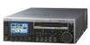
Chapter 1 Overview Names and Functions of Parts Front Panel q; Disc slot and EJECT button 1 On/standby 1 switch and indicator 2 ACCESS indicator 3 Remote control switch 4 LEVEL knob 5 PHONES jack ACCESS NETWORK LOCAL REMOTE LEVEL PHONES CH 1 CH 2 CH 3 F1 F2 CH 4 F3 F4 CHAPTER MENU MARK1 F5 EXPAND PAGE DISPLAY SUB THUMB IN CLIP NAIL SET RESET VARIABLE REC PRESET PB KEY INHI CLIP ESSENCE MENU MARK PREV PLAY NEXT MARK2 STOP SHIFT TOP F REV F FWD END STANDBY OUT REC VAR JOG SHUTTLE 6 SHIFT button 7 MENU button 8 SUB CLIP/CLIP MENU button 9 THUMBNAIL/ESSENCE MARK button EJECT qa Infrared sensor qs RESET button qd SET button 1 Display and function menu section 3 Arrow buttons Handle 2 Audio level adjustment section ACCESS NETWORK LOCAL REMOTE LEVEL PHONES CH 1 CH 2 CH 3 F1 F2 CH 4 F3 F4 CHAPTER MENU MARK1 F5 EXPAND PAGE DISPLAY SUB THUMB IN CLIP NAIL SET RESET VARIABLE REC PRESET PB KEY INHI CLIP ESSENCE MENU MARK PREV PLAY NEXT MARK2 STOP SHIFT TOP F REV F FWD END STANDBY OUT REC VAR JOG SHUTTLE EJECT 4 Shuttle/jog/ variable-speed playback control block 5 Recording/playback control block a On/standby 1 switch and indicator When the POWER switch (see page 24) on the rear panel is in the * (on) position, this switches the unit between the operating state (the indicator is lit green) and the standby state (the indicator is lit red). When the indicator is lit red, pressing this switch puts the unit into the operating state. The indicator initially flashes green and then lights green when the unit enters the operating state. When the indicator is lit green, pressing this switch puts the unit into the standby state. The indicator initially flashes green, and then lights red when the unit enters the standby state. When using the unit, normally leave the rear panel POWER switch in the * (on) position, and use this switch to switch the unit between the operating and standby states. b ACCESS indicator This lights blue while a disc is being accessed and while a file is open by a FAM or FTP connection. If the on/standby switch is pressed while this indicator is lit, the unit waits until access to the disc is completed before switching to the standby state. 15 Names and Functions of Parts
-
 1
1 -
2
-
3
-
4
-
5
-
6
-
7
-
8
-
9
-
 10
10 -
 11
11 -
 12
12 -
 13
13 -
 14
14 -
 15
15 -
 16
16 -
 17
17 -
 18
18 -
 19
19 -
 20
20 -
21
-
22
-
23
-
24
-
25
-
26
-
27
-
28
-
29
-
30
-
31
-
32
-
33
-
34
-
35
-
36
-
37
-
38
-
39
-
40
-
41
-
42
-
43
-
44
-
45
-
46
-
47
-
48
-
49
-
50
-
51
-
52
-
53
-
54
-
55
-
56
-
57
-
58
-
59
-
60
-
61
-
62
-
63
-
64
-
65
-
66
-
67
-
68
-
69
-
70
-
71
-
72
-
73
-
74
-
75
-
76
-
77
-
78
-
79
-
80
-
81
-
82
-
83
-
84
-
85
-
86
-
87
-
88
-
89
-
90
-
91
-
92
-
93
-
94
-
95
-
96
-
97
-
98
-
99
-
100
-
101
-
102
-
103
-
104
-
105
-
106
-
107
-
108
-
109
-
110
-
111
-
112
-
113
-
114
-
115
-
116
-
117
-
118
-
119
-
120
-
121
-
122
-
123
-
124
-
125
-
126
-
127
-
128
-
129
-
130
-
131
-
132
-
133
-
134
-
135
 |
 |
