Sony PDWF75 User Manual (PDW-F75 Professional Disc Recorder Operating Manual f - Page 21
Rear Panel, NEXT button, STOP/STANDBY button, STOP button, REC record button
 |
View all Sony PDWF75 manuals
Add to My Manuals
Save this manual to your list of manuals |
Page 21 highlights
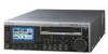
Chapter 1 Overview NEXT button: Press this button, turning it on, to jump to the first frame of the next clip or the next REC START essence mark. 1) END button: Press this button to jump to the last frame of the last clip or to the last REC START essence mark of the last clip. 1) You can perform a high-speed search in the forward direction by pressing the NEXT button together with the PLAY button. 1) The setting of OPERATIONAL FUNCTION >FIND MODE determines whether the unit jumps to clips or to REC START essence marks. When you play back clips recorded with the Clip Continuous Rec function (see page 50), you should set this menu item to "REC START EM". d STOP/STANDBY button This functions as a STOP button when pressed alone, and as a STANDBY button when pressed together with the SHIFT button. STOP button: Press this button, turning it on, to stop recording or playback. The frame at the stop position is displayed. STANDBY button: Press this button to put the unit into standby-off mode (the STOP button lights, and the STANDBY indicator goes off). Press it again to return to the original state (the STOP button lights, and the STANDBY indicator lights). This unit enters standby off mode automatically after a certain length of time passes. You can specify the length of time until the transition into standby off mode. For details, see the explanation of STILL TIMER in the setup menu (page 98). e REC (record) button Press this button together with the PLAY button to start recording. Recording starts on the unrecorded part of the disc. Press the STOP button to stop recording. A clip is created from the recorded section. Rear Panel 1 Analog video signal input/output section 2 Analog audio signal input/output section 3 Digital signal input/ output section 4 Digital audio signal input/output section 5 Timecode input/output section REF VIDEO INPUT COMPOSITE OUTPUT AUDIO MONITOR R L TIME CODE IN OUT -AC IN ANALOG HD INPUT Y/G PB /R AUDIO INPUT 1/3 2/4 AUDIO OUTPUT 1/3 2/4 DIGITAL 1/2 AUDIO (AES/EBU) INPUT 1/2 3/4 PB /B SYNS 3/4 HDSDI INPUT HDSDI OUTPUT 1 2 SDSDI OUTPUT OUTPUT MONITOR CONTROL RS232C REMOTE(9P) POWER S400 6 Power supply section 7 External device connection section 21 Names and Functions of Parts
-
 1
1 -
2
-
3
-
4
-
5
-
6
-
7
-
8
-
9
-
10
-
11
-
12
-
13
-
14
-
15
-
 16
16 -
 17
17 -
 18
18 -
 19
19 -
 20
20 -
 21
21 -
 22
22 -
 23
23 -
 24
24 -
 25
25 -
 26
26 -
27
-
28
-
29
-
30
-
31
-
32
-
33
-
34
-
35
-
36
-
37
-
38
-
39
-
40
-
41
-
42
-
43
-
44
-
45
-
46
-
47
-
48
-
49
-
50
-
51
-
52
-
53
-
54
-
55
-
56
-
57
-
58
-
59
-
60
-
61
-
62
-
63
-
64
-
65
-
66
-
67
-
68
-
69
-
70
-
71
-
72
-
73
-
74
-
75
-
76
-
77
-
78
-
79
-
80
-
81
-
82
-
83
-
84
-
85
-
86
-
87
-
88
-
89
-
90
-
91
-
92
-
93
-
94
-
95
-
96
-
97
-
98
-
99
-
100
-
101
-
102
-
103
-
104
-
105
-
106
-
107
-
108
-
109
-
110
-
111
-
112
-
113
-
114
-
115
-
116
-
117
-
118
-
119
-
120
-
121
-
122
-
123
-
124
-
125
-
126
-
127
-
128
-
129
-
130
-
131
-
132
-
133
-
134
-
135
 |
 |
