Sony PDWF75 User Manual (PDW-F75 Professional Disc Recorder Operating Manual f - Page 33
When using the editing functions of the, recorder connections using the S400, connector
 |
View all Sony PDWF75 manuals
Add to My Manuals
Save this manual to your list of manuals |
Page 33 highlights
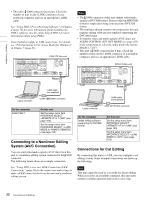
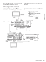
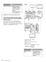
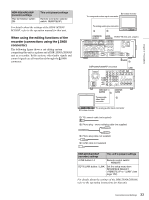
HDW-M2000/M2000P (recorder) settings 75Ω termination switch: ON This unit (player) settings Remote connector selector switch: REMOTE(9P) For details about the settings of the HDW-M2000/ M2000P, refer to the operation manual for that unit. When using the editing functions of the recorder (connections using the S400 connector) The following figure shows a cut editing system comprising this unit as a player and a DSR-2000A/2000AP unit as a recorder. In this system, video/audio signals and control signals are all transferred through the S400 connector. SD video monitor To composite video input connector To analog audio input connector 1 2 COMPOSITE AUDIO PDW-F75 (this unit, player) OUTPUT MONITOR REF VIDEO INPUT COMPOSITE OUTPUT AUDIO MONITOR R L TIME CODE IN OUT -AC IN ANALOG HD INPUT Y/G PB /R POWER AUDIO INPUT 1/3 2/4 AUDIO OUTPUT 1/3 2/4 DIGITAL 1/2 AUDIO (AES/EBU) INPUT 1/2 3/4 PB /B SYNS 3/4 HDSDI INPUT HDSDI OUTPUT 1 2 SDSDI OUTPUT OUTPUT MONITOR CONTROL RS232C REMOTE(9P) S400 DSR-2000A/2000AP (recorder) S400 4 i.LINK Chapter 2 Preparations VIDEO OUT 3 MONITOR (SUPER) 1 AUDIO To composite 3 video input connector To analog audio input connector SD video monitor 1: 75Ω coaxial cable (not supplied) 2: Phono plug - stereo miniplug cable (not supplied) 3: Phono plug cable (not supplied) 4: i.LINK cable (not supplied) DSR-2000A/2000AP (recorder) settings This unit's (player) settings i.LINK button: Lit Remote control switch: REMOTE SDTI/i.LINK button: i.LINK Set the setup menu item INTERFACE SELECT >REMOTE I/F to "i.LINK" (see page 103). For details about the settings of the DSR-2000A/2000AP, refer to the operating instructions for that unit. 33 Connections and Settings
-
 1
1 -
2
-
3
-
4
-
5
-
6
-
7
-
8
-
9
-
10
-
11
-
12
-
13
-
14
-
15
-
16
-
17
-
18
-
19
-
20
-
21
-
22
-
23
-
24
-
25
-
26
-
27
-
 28
28 -
 29
29 -
 30
30 -
 31
31 -
 32
32 -
 33
33 -
 34
34 -
 35
35 -
 36
36 -
 37
37 -
 38
38 -
39
-
40
-
41
-
42
-
43
-
44
-
45
-
46
-
47
-
48
-
49
-
50
-
51
-
52
-
53
-
54
-
55
-
56
-
57
-
58
-
59
-
60
-
61
-
62
-
63
-
64
-
65
-
66
-
67
-
68
-
69
-
70
-
71
-
72
-
73
-
74
-
75
-
76
-
77
-
78
-
79
-
80
-
81
-
82
-
83
-
84
-
85
-
86
-
87
-
88
-
89
-
90
-
91
-
92
-
93
-
94
-
95
-
96
-
97
-
98
-
99
-
100
-
101
-
102
-
103
-
104
-
105
-
106
-
107
-
108
-
109
-
110
-
111
-
112
-
113
-
114
-
115
-
116
-
117
-
118
-
119
-
120
-
121
-
122
-
123
-
124
-
125
-
126
-
127
-
128
-
129
-
130
-
131
-
132
-
133
-
134
-
135
 |
 |
