Sony PDWF75 User Manual (PDW-F75 Professional Disc Recorder Operating Manual f - Page 89
P1, HDSDI, ANALOG2, AES/EBU, Setting item, Description, COUNTER, CH 1/2, CH 3/4, STEREO
 |
View all Sony PDWF75 manuals
Add to My Manuals
Save this manual to your list of manuals |
Page 89 highlights
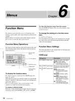
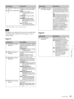
Setting item Description F3: A2 INPUT (audio input 2) F5: A4 INPUT (audio input 4) Selects the audio input signals assigned to audio channels 2 and 4. HDSDI: Audio signal multiplexed into HDSDI signal 1) ANALOG2: Analog 2 audio signal AES/EBU: Signals input to DIGITAL AUDIO (AES/ EBU) INPUT 1/2 and 3/4 connectors SG: Test signal from the internal signal generator 1) Only when HDSDI is selected as the video input. Note The signal name display flashes when the selected signal is not being input. Input the selected signal, or select another signal. Page P1 Setting item F1: CNTR SEL (counter selection) F2: MONI CH (monitor channel) F3: MONI SEL (monitor selection) F4: REC INH (recording inhibit) Description Selects the time data to display in the time data display section. TC: Timecode UB: User bits COUNTER: Elapsed recording or playback time Selects the audio channels to monitor. CH 1/2: Channels 1 and 2 CH 3/4: Channels 3 and 4 Selects the audio monitor signal output from the AUDIO MONITOR connector and the PHONES jack. STEREO: Assign the channels selected with MONI CH to left and right. MONO L (monaural L channel): Output one of the channels selected with MONI CH. MONO R (monaural R channel): Output one of the channels selected with MONI CH. MIX: Output monaural audio mixed from the channels selected with MONI CH. Turns recording inhibit mode on and off. ON: Recording inhibit mode on OFF: Recording inhibit mode off Setting item Description F5: CHAR SEL (Character information display) Turns the display of character information in the monitor video section of the LCD panel and on an external monitor on and off. ON: Character information on OFF: Character information off LCD: Character information on for the LCD panel only When "ON" is selected, you can turn the superimposition of character information on and off for the various output connectors. To do so, set the setup menu items DISPLAY CONTROL >HD CHARA and DISPLAY CONTROL >SD CHARA (see page 97). Page P2 Setting item F1: TCG (timecode generator) Description Sets the operation of the internal timecode generator. INT (internal): The count value advances from a preset initial value, or advances consecutively from the timecode of the last frame recorded on the disc. EXT (external): Synchronize to the timecode input to the TIME CODE IN connector. SDI: Synchronize to the timecode of the signal input to the HDSDI connector. Chapter 6 Menus 89 Function Menu
-
 1
1 -
2
-
3
-
4
-
5
-
6
-
7
-
8
-
9
-
10
-
11
-
12
-
13
-
14
-
15
-
16
-
17
-
18
-
19
-
20
-
21
-
22
-
23
-
24
-
25
-
26
-
27
-
28
-
29
-
30
-
31
-
32
-
33
-
34
-
35
-
36
-
37
-
38
-
39
-
40
-
41
-
42
-
43
-
44
-
45
-
46
-
47
-
48
-
49
-
50
-
51
-
52
-
53
-
54
-
55
-
56
-
57
-
58
-
59
-
60
-
61
-
62
-
63
-
64
-
65
-
66
-
67
-
68
-
69
-
70
-
71
-
72
-
73
-
74
-
75
-
76
-
77
-
78
-
79
-
80
-
81
-
82
-
83
-
 84
84 -
 85
85 -
 86
86 -
 87
87 -
 88
88 -
 89
89 -
 90
90 -
 91
91 -
 92
92 -
 93
93 -
 94
94 -
95
-
96
-
97
-
98
-
99
-
100
-
101
-
102
-
103
-
104
-
105
-
106
-
107
-
108
-
109
-
110
-
111
-
112
-
113
-
114
-
115
-
116
-
117
-
118
-
119
-
120
-
121
-
122
-
123
-
124
-
125
-
126
-
127
-
128
-
129
-
130
-
131
-
132
-
133
-
134
-
135
 |
 |
