Sony PDWF75 User Manual (PDW-F75 Professional Disc Recorder Operating Manual f - Page 88
Menus, Function Menu, Function Menu Operations
 |
View all Sony PDWF75 manuals
Add to My Manuals
Save this manual to your list of manuals |
Page 88 highlights
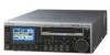
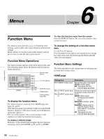
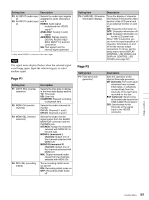
Menus 6 Chapter Chapter 6 Menus Function Menu To clear the function menu from the screen Press the DISPLAY button. The size of the monitor video section increases. The function menu provides access to frequently used settings, such as input video signal selection and timecode settings. Menu settings are stored in nonvolatile memory and are preserved even after the unit is powered off. Function Menu Operations The function menu appears on the LCD panel of this unit. The following figure shows the buttons used in function menu operations. 0 0 -12 -12 -20 -20 -30 -30 -40 -40 -60 1 2 -60 3 4 4CH 16 BIT 3+4 MPEG HD SP 1080 60I VITC COOO1 REM:077M 00: 00 .00: 00 TCG EXT TC MODE PRESET RUN MODE REC RUN TC/VITC VITC DF/NDF NDF P2 Display F1 F2 F3 F4 F5 PAGE DISPLAY Monitor video section F1 to F5 buttons DISPLAY button PAGE button Function Menu (page 88) To display the function menu The function menu is made up of the HOME page and pages P1 and P2. If the function menu is not already visible, press the PAGE button to display it. (The most recently accessed function menu page appears.) The size of the monitor video section changes to the smallest size when the function menu appears. To display a different page Each press of the PAGE button displays the next function menu page in the order HOME t P1 t P2 t HOME... To change the setting of a function menu item Use the F1 to F5 buttons. Press the button to the right of each setting item to change the value of the item. Keep pressing the button until the value you want appears. Function Menu Settings The following tables list the setting items on each page and describe their setting values. HOME page Setting item Description F1: V INPUT (video input) Selects the video input signal. HDSDI: HDSDI signal SG: Test signal from the internal signal generator F2: A1 INPUT (audio input 1) F4: A3 INPUT (audio input 3) Selects the audio input signals assigned to audio channels 1 and 3. HDSDI: Audio signal multiplexed into HDSDI signal 1) ANALOG1: Analog 1 audio signal AES/EBU: Signals input to DIGITAL AUDIO (AES/ EBU) INPUT 1/2 and 3/4 connectors SG: Test signal from the internal signal generator 88 Function Menu
-
 1
1 -
2
-
3
-
4
-
5
-
6
-
7
-
8
-
9
-
10
-
11
-
12
-
13
-
14
-
15
-
16
-
17
-
18
-
19
-
20
-
21
-
22
-
23
-
24
-
25
-
26
-
27
-
28
-
29
-
30
-
31
-
32
-
33
-
34
-
35
-
36
-
37
-
38
-
39
-
40
-
41
-
42
-
43
-
44
-
45
-
46
-
47
-
48
-
49
-
50
-
51
-
52
-
53
-
54
-
55
-
56
-
57
-
58
-
59
-
60
-
61
-
62
-
63
-
64
-
65
-
66
-
67
-
68
-
69
-
70
-
71
-
72
-
73
-
74
-
75
-
76
-
77
-
78
-
79
-
80
-
81
-
82
-
 83
83 -
 84
84 -
 85
85 -
 86
86 -
 87
87 -
 88
88 -
 89
89 -
 90
90 -
 91
91 -
 92
92 -
 93
93 -
94
-
95
-
96
-
97
-
98
-
99
-
100
-
101
-
102
-
103
-
104
-
105
-
106
-
107
-
108
-
109
-
110
-
111
-
112
-
113
-
114
-
115
-
116
-
117
-
118
-
119
-
120
-
121
-
122
-
123
-
124
-
125
-
126
-
127
-
128
-
129
-
130
-
131
-
132
-
133
-
134
-
135
 |
 |
