Sony PDWF75 User Manual (PDW-F75 Professional Disc Recorder Operating Manual f - Page 24
External device connection AV/C Audio/Video Control connection
 |
View all Sony PDWF75 manuals
Add to My Manuals
Save this manual to your list of manuals |
Page 24 highlights
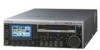
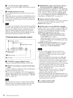
Chapter 1 Overview a -AC IN (AC power input) connector Connect to an AC power supply with the power cord (not supplied). b POWER (main power) switch Press the + side to power on the unit. Press the a side to power off. When using the unit, normally leave the POWER switch in the + (on) position, and use the on/standby switch on the front panel to switch the unit between the operating state and standby state. Note If you press the on/standby switch on the front panel while the unit is in the operating state, the unit saves its data and then enters the standby state (the on/standby indicator lights red). Before turning the main power off, always check to be sure that the unit is in the standby state, and then push the main power switch to the a side. 7 External device connection section 1 CONTROL connector 2 RS232C connector 3 REMOTE(9P) connector CONTROL RS232C 4 Remote connector selector switch 5 S400 connector 6 U terminal REMOTE(9P) S400 a CONTROL connector (minijack 4-pole) Connect the optional RM-LG2 Remote Control Unit. b RS232C (serial interface) connector (D-sub 9-pin, male) Connect a computer or other device with a serial interface to control this unit from that device. When you use this connector, set the remote connector selector switch to the RS232C side, and set INTERFACE SELECT >REMOTE I/F in the setup menu to "9PIN/RS232C" (see page 103). Note This unit cannot be used as a recorder for linear editing. When it receives an assemble command, this unit starts normal recording operation and creates a new clip. c REMOTE(9P) (remote control 9-pin) connector (D-sub 9-pin, RS-422A compliant, female) To control this unit from a controller or VTR supporting the RS-422A Sony 9-pin VTR protocol, connect the device to this connector. When you use this connector, set the remote connector selector switch to the REMOTE(9P) side, and set INTERFACE SELECT > REMOTE I/F in the setup menu to "9PIN/RS-232C" (see page 103). d Remote connector selector switch Push this switch to the side of the remote control connector you are using, either the RS232C connector or the REMOTE (9P) connector. e S400 connector (6-pin, IEEE1394 compliant) Connect a DV device or computer using an i.LINK cable. The following connection types are supported. They are selected by setting INTERFACE SELECT >i.LINK MODE in the setup menu (see page 103). AV/C (Audio/Video Control) connection: Output DVCAM format digital video and audio signals (i.LINK MODE set to "AV/C"). Audio output signals are 2ch or 4ch, as selected by AUDIO CONTROL >DV OUT MODE in the setup menu (see page 102). FAM (file access mode) connection: Input and output files between this unit and a computer (i.LINK MODE set to "FAM (PC REMOTE)"). Notes • If video or audio signals from an external device connected to the S400 connector fail to be output, disconnect the i.LINK cable and connect it again, pushing it straight in. • Before connecting or disconnecting an i.LINK cable between this unit and a device with a 6-pin i.LINK connector, power off the device and disconnect its power cord from the electrical outlet. If the i.LINK cable is connected or disconnected with the device's power plug still connected, high voltage (8 to 40 V) from the device's i.LINK connector can flow into this unit, possibly damaging the unit. • When connecting this unit to a device with a 6-pin i.LINK connector, connect to the 6-pin i.LINK connector of the other device first. • Except in playback modes (jog and shuttle modes, etc.), audio signals output from this connector and monitored on another device may sound different from the audio signals played back on this unit. f U (signal ground) terminal Connect to the system ground. 24 Names and Functions of Parts
-
 1
1 -
2
-
3
-
4
-
5
-
6
-
7
-
8
-
9
-
10
-
11
-
12
-
13
-
14
-
15
-
16
-
17
-
18
-
 19
19 -
 20
20 -
 21
21 -
 22
22 -
 23
23 -
 24
24 -
 25
25 -
 26
26 -
 27
27 -
 28
28 -
 29
29 -
30
-
31
-
32
-
33
-
34
-
35
-
36
-
37
-
38
-
39
-
40
-
41
-
42
-
43
-
44
-
45
-
46
-
47
-
48
-
49
-
50
-
51
-
52
-
53
-
54
-
55
-
56
-
57
-
58
-
59
-
60
-
61
-
62
-
63
-
64
-
65
-
66
-
67
-
68
-
69
-
70
-
71
-
72
-
73
-
74
-
75
-
76
-
77
-
78
-
79
-
80
-
81
-
82
-
83
-
84
-
85
-
86
-
87
-
88
-
89
-
90
-
91
-
92
-
93
-
94
-
95
-
96
-
97
-
98
-
99
-
100
-
101
-
102
-
103
-
104
-
105
-
106
-
107
-
108
-
109
-
110
-
111
-
112
-
113
-
114
-
115
-
116
-
117
-
118
-
119
-
120
-
121
-
122
-
123
-
124
-
125
-
126
-
127
-
128
-
129
-
130
-
131
-
132
-
133
-
134
-
135
 |
 |
