Sony PDWF75 User Manual (PDW-F75 Professional Disc Recorder Operating Manual f - Page 31
When using an editing control unit, HDSDI, OUTPUT, INPUT, REMOTE9P, VIDEO IN, REMOTE 1-IN9P, SUPER - pdw f75 manual
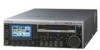 |
View all Sony PDWF75 manuals
Add to My Manuals
Save this manual to your list of manuals |
Page 31 highlights
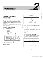
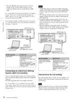
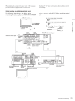
Chapter 2 Preparations When making the connections, also refer to the manuals provided with the equipment to be connected. See page 34 for more information about editing control unit settings. When using an editing control unit The following figure shows a cut editing system comprising this unit as a player, an HDW-M2000/M2000P HD video monitor unit as a recorder, and a BVE-700A as an editing control unit. 1: 75Ω coaxial cable (not supplied) Reference video signal To analog audio input connector To HDSDI input connector 3 1 2: 9-pin remote control cable (not supplied) 3: Phono plug - stereo miniplug cable (not supplied) 1 REF VIDEO INPUT REF VIDEO INPUT HDSDI OUTPUT AUDIO MONITOR PDW-F75 (this unit, player) REF VIDEO INPUT COMPOSITE OUTPUT AUDIO MONITOR R L TIME CODE IN OUT -AC IN ANALOG HD INPUT Y/G PB /R AUDIO INPUT 1/3 2/4 AUDIO OUTPUT 1/3 2/4 DIGITAL 1/2 AUDIO (AES/EBU) INPUT 1/2 3/4 PB /B SYNS 3/4 HDSDI INPUT HDSDI OUTPUT 1 2 SDSDI OUTPUT OUTPUT MONITOR CONTROL RS232C REMOTE(9P) POWER S400 HDSDI OUTPUT Remote connector selector switch 1 REMOTE(9P) 2 1 REF VIDEO INPUT 75Ω HDSDI INPUT REF VIDEO INPUT 1 HDW-M2000/M2000P (recorder) HDSDI OUTPUT 3 1 REMOTE 1-IN(9P) (SUPER) REF VIDEO IN To HDSDI input connector PLAYER-1 SDI OUT MONITOR OUT SWER VIDEO OUT2 VIDEO OUT1 MIXER RECORDER SDI IN PLAYER-3 TITLE RECORDER AUX/ PLAYER-3 PLAYER-2 PLAYER-2 PLAYER-1 PLAYER-1 REF VIDEO IN NETWORK PANEL GPI EDL AC IN RECORDER BVE-700A (editing control unit) 2 HD video monitor 31 Connections and Settings
-
 1
1 -
2
-
3
-
4
-
5
-
6
-
7
-
8
-
9
-
10
-
11
-
12
-
13
-
14
-
15
-
16
-
17
-
18
-
19
-
20
-
21
-
22
-
23
-
24
-
25
-
 26
26 -
 27
27 -
 28
28 -
 29
29 -
 30
30 -
 31
31 -
 32
32 -
 33
33 -
 34
34 -
 35
35 -
 36
36 -
37
-
38
-
39
-
40
-
41
-
42
-
43
-
44
-
45
-
46
-
47
-
48
-
49
-
50
-
51
-
52
-
53
-
54
-
55
-
56
-
57
-
58
-
59
-
60
-
61
-
62
-
63
-
64
-
65
-
66
-
67
-
68
-
69
-
70
-
71
-
72
-
73
-
74
-
75
-
76
-
77
-
78
-
79
-
80
-
81
-
82
-
83
-
84
-
85
-
86
-
87
-
88
-
89
-
90
-
91
-
92
-
93
-
94
-
95
-
96
-
97
-
98
-
99
-
100
-
101
-
102
-
103
-
104
-
105
-
106
-
107
-
108
-
109
-
110
-
111
-
112
-
113
-
114
-
115
-
116
-
117
-
118
-
119
-
120
-
121
-
122
-
123
-
124
-
125
-
126
-
127
-
128
-
129
-
130
-
131
-
132
-
133
-
134
-
135
 |
 |
