Sony PDWF75 User Manual (PDW-F75 Professional Disc Recorder Operating Manual f - Page 38
Input and Output Signals in 24P (23.98P) Mode, Recording in 24P (23.98P) Mode
 |
View all Sony PDWF75 manuals
Add to My Manuals
Save this manual to your list of manuals |
Page 38 highlights
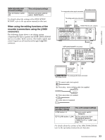
Chapter 2 Preparations 14Press the M/MARK1 or m/MARK2 button to select one of the following. 23.98PsF: Output as 23.98P. 2-3 PULL DOWN: Output after pulldown conversion to 59.94i. 15Press the SET button. A confirmation message appears. 16Press the SET button to confirm the changes, or the RESET button to cancel them. If you have pressed the SET button, power the unit off and on again to enable the changes. Input and Output Signals in 24P (23.98P) Mode The following tables show the signals input and output by the unit when "23.98PsF" and "2-3 PULL DOWN" are selected. Input and output signals I/O Type 23.98PsF 2-3 PULL DOWN Input signals Reference video input 23.98PsF 59.94i reference signal reference signal HDSDI input 23.98PsF video and audio signals Input LTC input timecode HDSDI LTC input 24-frame timecode Output signals HDSDI 23.98PsF video Video and output and audio audio signals signals pulled down to SDSDI output No output 59.94i Composite output i.LINK DV output i.LINK TS output Timecode LTC output output HDSDI LTC/ VITC output SDSDI RP188 LTC output 24-frame timecode - 30-frame timecode after pulldown conversion SDSDI VITC - output COMPOSITE - VITC output Timecode display Type 23.98PsF 2-3 PULL DOWN LTC display 24-frame timecode PDT display VITC display - 30-frame timecode 24-frame timecode after pulldown conversion COUNTER display 24-frame signals 30-frame signals after pulldown conversion Timecode in remote timecode mode Type 23.98PsF 2-3 PULL DOWN 9-pin preset timecode 24-frame timecode 9-pin preset 24-frame signals timer 1 (Counter) 30-frame signals after pulldown conversion 9-pin scene timecode 24-frame timecode 30-frame timecode after pulldown conversion 9-pin scene 24-frame signals timer 1 (Counter) 30-frame signals after pulldown conversion For more information about remote timecode mode, refer to the REMOTE (9-pin) Protocol Manual for the PDW series (not supplied). Recording in 24P (23.98P) Mode Recording frame sequence and clip length See the following figure for the frame sequence. In 24P (23.98P) mode, recording start and stop timing is adjusted so that a recorded sequence always begins with an "A-frame" and ends with a "D-frame". As a result, the number of frames in a clip is always a multiple of 4. Recording timecode When you preset timecode manually, select a multiple of 4 as the number of frames in the timecode, and adjust so that the preset timing begins with an "A-frame". The unit will then adjust so that the timecode at the start of recorded clips will have a number of frames that is a multiple of 4. Notes • The above adjustments are not carried out when you preset timecode remotely. • No adjustments are made when you record external timecode. Therefore the number of frames in the 38 24P (23.98P) Mode Settings
-
 1
1 -
2
-
3
-
4
-
5
-
6
-
7
-
8
-
9
-
10
-
11
-
12
-
13
-
14
-
15
-
16
-
17
-
18
-
19
-
20
-
21
-
22
-
23
-
24
-
25
-
26
-
27
-
28
-
29
-
30
-
31
-
32
-
 33
33 -
 34
34 -
 35
35 -
 36
36 -
 37
37 -
 38
38 -
 39
39 -
 40
40 -
 41
41 -
 42
42 -
 43
43 -
44
-
45
-
46
-
47
-
48
-
49
-
50
-
51
-
52
-
53
-
54
-
55
-
56
-
57
-
58
-
59
-
60
-
61
-
62
-
63
-
64
-
65
-
66
-
67
-
68
-
69
-
70
-
71
-
72
-
73
-
74
-
75
-
76
-
77
-
78
-
79
-
80
-
81
-
82
-
83
-
84
-
85
-
86
-
87
-
88
-
89
-
90
-
91
-
92
-
93
-
94
-
95
-
96
-
97
-
98
-
99
-
100
-
101
-
102
-
103
-
104
-
105
-
106
-
107
-
108
-
109
-
110
-
111
-
112
-
113
-
114
-
115
-
116
-
117
-
118
-
119
-
120
-
121
-
122
-
123
-
124
-
125
-
126
-
127
-
128
-
129
-
130
-
131
-
132
-
133
-
134
-
135
 |
 |
