Sony PFM-510A1WU Operating Instructions - Page 10
Left Connector Panel, Remote Commander RM-921, MONITOR OUT AUDIO L/R jacks phono
 |
View all Sony PFM-510A1WU manuals
Add to My Manuals
Save this manual to your list of manuals |
Page 10 highlights
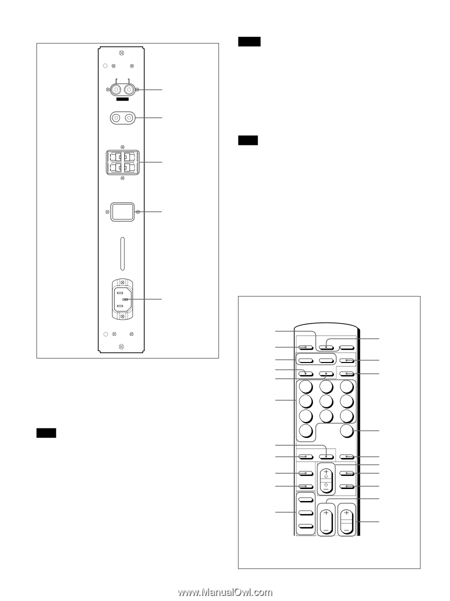
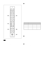
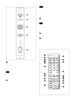
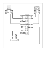
Location and Function of Parts and Controls Left Connector Panel MONITOR OUT AUDIO R L VARIABLE CONTROL S IN OUT SPEAKERS (6-16 Ω) + + R- L - 1 2 3 SERVICE CODE 8.8. 4 5 Notes • If you connect the CONTROL S IN jack to the other equipment's CONTROL S OUT jack, you cannot operate the monitor with the Remote Commander. • You can use the stereo cable with mini plug instead of the control S cable. 3 SPEAKERS L/R terminals Connect to speakers with 6 to 16 ohms impedance. Note Do not connect the speaker's cord to the monitor and to an amplifier simultaneously, or an excessive electric current might flow from the amplifier and damage the monitor. 4 SERVICE CODE indicator The indicator is only for qualified personnel. 5 -AC IN socket Connect the supplied AC power cord to this socket and to a wall outlet. Once you connect the AC power cord, the monitor turns to standby mode. Remote Commander RM-921 AC IN 1 MONITOR OUT AUDIO (L/R) jacks (phono type) Output the signal input from the AUDIO IN jacks. Connect to the audio inputs of an audio amplifier (not supplied). Note These jacks are variable outputs. Set the volume to maximum position to set the output level to 500 mVrms. 2 CONTROL S IN/OUT jacks (mini jacks) Connect to the CONTROL S jacks of video equipment or another monitors. Then you can simultaneously control all equipment with a single Remote Commander. To control equipment by aiming the supplied Remote Commander to the remote control detector of the monitor, connect the CONTROL S OUT jack of the monitor and the CONTROL S IN jack of other equipment. 10 (GB) 1 qs 2 MUTING DISPLAY POWER 3 RGB1 RGB2 YUV qd 4 LINE Y/C MTS/MPX qf 5 123 6 456 789 10/0 CH qg 7 8 STILL ZOOM DEGAUSS qh POWER ON SELECT MENU qj 9 qk 0 OFF ENTER ql» ON w;... qa SET VOL CH OFF wa ID MODE
-
 1
1 -
2
-
3
-
4
-
 5
5 -
 6
6 -
 7
7 -
 8
8 -
 9
9 -
 10
10 -
 11
11 -
 12
12 -
 13
13 -
 14
14 -
 15
15 -
16
-
17
-
18
-
19
-
20
-
21
-
22
-
23
-
24
-
25
-
26
-
27
-
28
-
29
-
30
-
31
-
32
-
33
-
34
-
35
-
36
-
37
-
38
-
39
-
40
-
41
-
42
-
43
-
44
-
45
-
46
-
47
-
48
-
49
-
50
-
51
-
52
-
53
-
54
-
55
-
56
-
57
-
58
-
59
-
60
-
61
-
62
-
63
-
64
-
65
-
66
-
67
-
68
-
69
-
70
-
71
-
72
-
73
-
74
-
75
-
76
-
77
-
78
-
79
-
80
-
81
-
82
-
83
-
84
-
85
-
86
-
87
-
88
-
89
-
90
-
91
-
92
-
93
-
94
-
95
-
96
-
97
-
98
-
99
-
100
-
101
-
102
-
103
-
104
-
105
-
106
-
107
-
108
-
109
-
110
-
111
-
112
-
113
-
114
-
115
-
116
-
117
-
118
-
119
-
120
-
121
-
122
-
123
-
124
-
125
-
126
-
127
-
128
-
129
-
130
-
131
-
132
-
133
-
134
-
135
-
136
-
137
-
138
-
139
-
140
-
141
-
142
-
143
-
144
-
145
-
146
-
147
-
148
-
149
-
150
-
151
-
152
-
153
-
154
-
155
-
156
-
157
-
158
-
159
-
160
-
161
-
162
-
163
-
164
-
165
-
166
-
167
-
168
-
169
-
170
-
171
-
172
-
173
-
174
-
175
-
176
-
177
-
178
-
179
-
180
-
181
-
182
-
183
-
184
 |
 |