Sony PFM-510A1WU Operating Instructions - Page 7
Control Panel, Y/C button
 |
View all Sony PFM-510A1WU manuals
Add to My Manuals
Save this manual to your list of manuals |
Page 7 highlights
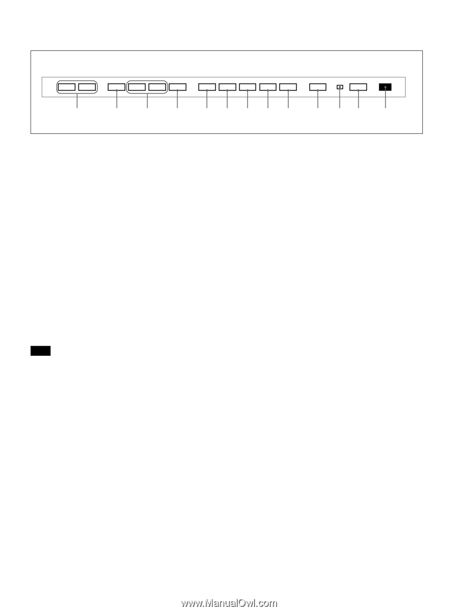
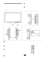
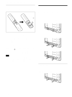
Control Panel Location and Function of Parts and Controls VOL - VOL + MENU m M ENT RGB1 YUV RGB2 LINE Y/C CTRL 1 qd qs qa 0 98765 4 32 1 1 Remote control detector Receives the beam from the Remote Commander. 2 1 (standby) switch/1 (standby) indicator Press to turn the monitor on. Press again to go back to the standby mode. The 1 (standby) indicator lights up in red in the standby mode. When the 1 indicator flashes, see "Self-diagnosis Function" on page 26 (GB). 3 Power indicator Lights up when the monitor is turned on. 4 CTRL (control) button To operate the buttons on the control panel, first press this button. Then the buttons light up or flash that show they can be operated. Press again to deactivate them. Note The buttons (except for 1 (standby) switch 2) on the control panel do not function if you do not press the CTRL button first. 5 Y/C button Select the signal input from the Y/C IN jack in the LINE connectors. 6 LINE button Select the signal input from the VIDEO IN connector in the LINE connectors. 7 RGB2 button Select the signal input from the RGB2 connectors. 8 YUV button Select the component signal input from the RGB1 connectors. 9 RGB1 button Select the RGB signal input from the RGB1 connectors. 0 ENT (enter) button Press to select the desired item in a menu. qa M/m buttons Press to move the cursor (B) to an item or to adjust value in a menu. qs MENU button Press to make the menu appear. qd VOL (volume) +/- buttons Press the + button to increase the volume, or the - button to decrease the volume. 7 (GB)
-
 1
1 -
 2
2 -
 3
3 -
 4
4 -
 5
5 -
 6
6 -
 7
7 -
 8
8 -
 9
9 -
 10
10 -
 11
11 -
 12
12 -
13
-
14
-
15
-
16
-
17
-
18
-
19
-
20
-
21
-
22
-
23
-
24
-
25
-
26
-
27
-
28
-
29
-
30
-
31
-
32
-
33
-
34
-
35
-
36
-
37
-
38
-
39
-
40
-
41
-
42
-
43
-
44
-
45
-
46
-
47
-
48
-
49
-
50
-
51
-
52
-
53
-
54
-
55
-
56
-
57
-
58
-
59
-
60
-
61
-
62
-
63
-
64
-
65
-
66
-
67
-
68
-
69
-
70
-
71
-
72
-
73
-
74
-
75
-
76
-
77
-
78
-
79
-
80
-
81
-
82
-
83
-
84
-
85
-
86
-
87
-
88
-
89
-
90
-
91
-
92
-
93
-
94
-
95
-
96
-
97
-
98
-
99
-
100
-
101
-
102
-
103
-
104
-
105
-
106
-
107
-
108
-
109
-
110
-
111
-
112
-
113
-
114
-
115
-
116
-
117
-
118
-
119
-
120
-
121
-
122
-
123
-
124
-
125
-
126
-
127
-
128
-
129
-
130
-
131
-
132
-
133
-
134
-
135
-
136
-
137
-
138
-
139
-
140
-
141
-
142
-
143
-
144
-
145
-
146
-
147
-
148
-
149
-
150
-
151
-
152
-
153
-
154
-
155
-
156
-
157
-
158
-
159
-
160
-
161
-
162
-
163
-
164
-
165
-
166
-
167
-
168
-
169
-
170
-
171
-
172
-
173
-
174
-
175
-
176
-
177
-
178
-
179
-
180
-
181
-
182
-
183
-
184
 |
 |