Sony PFM-510A1WU Operating Instructions - Page 8
Right Connector Panel, R R-Y/G Y/B B-Y IN BNC-type
 |
View all Sony PFM-510A1WU manuals
Add to My Manuals
Save this manual to your list of manuals |
Page 8 highlights
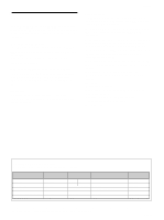
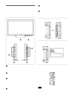
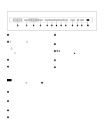
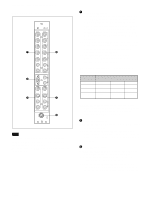
Location and Function of Parts and Controls Right Connector Panel 1 2 3 RGB 1 IN OUT R R-Y G Y B B-Y HD/ COMP VD SYNC L AUDIO R RGB 2 RGB IN L AUDIO IN R VIDEO Y/C L AUDIO R IN OUT LINE REMOTE (RS-232C) 4 5 6 Note The image enhancing process for video signals (NTSC, PAL) works only for composite (Y/C) or component (Y/R-Y/B-Y) input. The image from the RGB input may looked blurred. This is normal. 1 RGB1 IN connectors R (R-Y)/G (Y)/B (B-Y) IN (BNC-type): Input the analog RGB signal or component signal. Connect to the RGB signal or component (Y/B-Y/R-Y) signal output of a computer or video equipment. This unit also accepts the HD analog component (Y/PB/PR) signal. Input the PB signal to the B (BY) IN connector and PR signal to the R (R-Y) IN connector. HD/COMP IN (BNC-type): Input the H sync signal or composite sync signal. Connect to the H sync signal or composite sync signal output of a computer or video equipment. VD IN (BNC-type): Input the V sync signal. Connect to the V sync signal output of a computer or video equipment. External sync signal is selected automatically. See the priority chart below. Input Input sync signals connector HD/COMP IN H Sync Comp Sync VD IN V Sync - G(Y) IN Sync on G Sync on G Sync signals H Sync to be selected V Sync Comp Sync - - Sync on G Sync on G AUDIO IN (L/R) (phono type): Input the audio signal. Connect to the audio output of a computer or video equipment. Connect to the channel L when the audio signal is monaural. 2 RGB2 IN connectors RGB IN (D-sub 15-pin): Connect to the RGB signal output of a computer. AUDIO IN (L/R) (phono type): Input the audio signal. Connect to the audio output of a computer. Connect to the channel L when the audio signal is monaural. 3 LINE IN connectors VIDEO IN (BNC-type): Connect to the composite video signal output of the video equipment. Y/C IN (Mini DIN 4-pin): Connect to the Y/C signal output of the video equipment. AUDIO IN (L/R) (phono type): Connect to the audio output of the video equipment. Connect to the channel L when the audio signal is monaural. 8 (GB)
-
 1
1 -
2
-
 3
3 -
 4
4 -
 5
5 -
 6
6 -
 7
7 -
 8
8 -
 9
9 -
 10
10 -
 11
11 -
 12
12 -
 13
13 -
14
-
15
-
16
-
17
-
18
-
19
-
20
-
21
-
22
-
23
-
24
-
25
-
26
-
27
-
28
-
29
-
30
-
31
-
32
-
33
-
34
-
35
-
36
-
37
-
38
-
39
-
40
-
41
-
42
-
43
-
44
-
45
-
46
-
47
-
48
-
49
-
50
-
51
-
52
-
53
-
54
-
55
-
56
-
57
-
58
-
59
-
60
-
61
-
62
-
63
-
64
-
65
-
66
-
67
-
68
-
69
-
70
-
71
-
72
-
73
-
74
-
75
-
76
-
77
-
78
-
79
-
80
-
81
-
82
-
83
-
84
-
85
-
86
-
87
-
88
-
89
-
90
-
91
-
92
-
93
-
94
-
95
-
96
-
97
-
98
-
99
-
100
-
101
-
102
-
103
-
104
-
105
-
106
-
107
-
108
-
109
-
110
-
111
-
112
-
113
-
114
-
115
-
116
-
117
-
118
-
119
-
120
-
121
-
122
-
123
-
124
-
125
-
126
-
127
-
128
-
129
-
130
-
131
-
132
-
133
-
134
-
135
-
136
-
137
-
138
-
139
-
140
-
141
-
142
-
143
-
144
-
145
-
146
-
147
-
148
-
149
-
150
-
151
-
152
-
153
-
154
-
155
-
156
-
157
-
158
-
159
-
160
-
161
-
162
-
163
-
164
-
165
-
166
-
167
-
168
-
169
-
170
-
171
-
172
-
173
-
174
-
175
-
176
-
177
-
178
-
179
-
180
-
181
-
182
-
183
-
184
 |
 |
