Stihl MS 251 Instruction Manual - Page 110
Models with manual fuel pump, Machines with QuickStop Super, All models, Install the handlebar
 |
View all Stihl MS 251 manuals
Add to My Manuals
Save this manual to your list of manuals |
Page 110 highlights
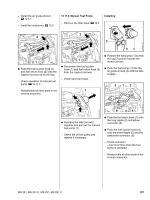
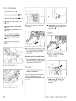
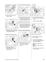
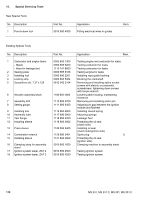
Machines with QuickStop Super All models 12 1 4 2310RA232 TG 2310RA416 TG 2310RA058 TG : Insert and tighten down the screw (1) firmly. 1 : Pass the fuel hose (1) upwards through the opening (arrow) and into the engine housing. 2310RA386 TG 3 1 : Push the brake cable (1), short hook (4) first, passed the righthand side of the fuel hose (3) and through the opening (arrow). Models with manual fuel pump : Push the brake cable (1), short hook (4) first, passed the righthand side of the fuel hose (3) and the fuel return hose (2) and through the opening (arrow). Machines with QuickStop Super : Fit the antivibration spring (1) in the recess (arrow) in the engine housing. - Install the handlebar, b 9.4 2 1 2310RA417 TG Models with manual fuel pump 1 : Pass the fuel return hose (1) upwards through the opening (arrow) and into the engine housing. 2310RA402 TG 12 : Push the brake cable (1), short hook (2) first, through the bore (arrow) in the engine housing. 2310RA415 TG : Lift the tank housing (2). : Insert and tighten down the screw (1) firmly. - On models with QuickStop Super, connect the brake cable to the brake lever, b 5.4.2 - Install the air guide shroud, b 12.4 Models with manual fuel pump, b 12.4.1 - Reassemble all other parts in the reverse sequence. MS 231, MS 231 C, MS 251, MS 251 C 109
-
 1
1 -
2
-
3
-
4
-
5
-
6
-
7
-
8
-
9
-
10
-
11
-
12
-
13
-
14
-
15
-
16
-
17
-
18
-
19
-
20
-
21
-
22
-
23
-
24
-
25
-
26
-
27
-
28
-
29
-
30
-
31
-
32
-
33
-
34
-
35
-
36
-
37
-
38
-
39
-
40
-
41
-
42
-
43
-
44
-
45
-
46
-
47
-
48
-
49
-
50
-
51
-
52
-
53
-
54
-
55
-
56
-
57
-
58
-
59
-
60
-
61
-
62
-
63
-
64
-
65
-
66
-
67
-
68
-
69
-
70
-
71
-
72
-
73
-
74
-
75
-
76
-
77
-
78
-
79
-
80
-
81
-
82
-
83
-
84
-
85
-
86
-
87
-
88
-
89
-
90
-
91
-
92
-
93
-
94
-
95
-
96
-
97
-
98
-
99
-
100
-
101
-
102
-
103
-
104
-
 105
105 -
 106
106 -
 107
107 -
 108
108 -
 109
109 -
 110
110 -
 111
111 -
 112
112 -
 113
113 -
 114
114
 |
 |
