Stihl MS 251 Instruction Manual - Page 73
Throttle Trigger/Lockout Lever, rear handle so that
 |
View all Stihl MS 251 manuals
Add to My Manuals
Save this manual to your list of manuals |
Page 73 highlights
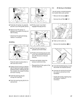
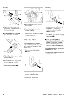
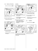
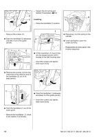
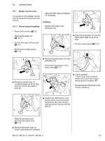
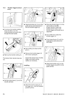
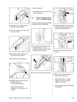
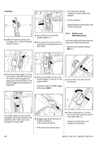
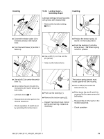
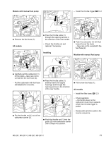
10.2 Throttle Trigger/Lockout Lever 1 2 3 2 1 1 2310RA170 TG 2310RA167 TG 5902RA307 TG 1 : To remove the handle molding, press the tabs (1) on the underside apart and push them through the rear handle. 1 : Take the throttle rod (1) out of the guide (arrow) and disconnect it from the throttle trigger (2). 2 4 1 3 : Place the throttle trigger (1) in the rear handle so that the tongue (arrow) is within the handle and the holes in the throttle trigger and handle are in alignment. : Use a drift (2) to center the throttle trigger (1). : Drive home the pin (3) until it is recessed by same amount at both sides. 2310RA168 TG 2310RA171 TG 2310RA165 TG : Use a drift (2) to drive out the pin (1). 1 : Remove the throttle trigger (3) 2 : Remove the handle molding (1). with torsion spring (4). The lockout lever (arrow) may pop out. - Inspect the lockout lever, throttle trigger and torsion spring, replace as necessary. Installing : Attach the throttle rod (1) to the throttle trigger (2) and fit it in the guide (arrow). 1 1 2 2310RA166 TG 2310RA169 TG : Pull the lockout lever (1) out of its mounts (arrows). : Attach the torsion spring (1) to the trigger (2) - note the installed position (arrow). 72 MS 231, MS 231 C, MS 251, MS 251 C
-
 1
1 -
2
-
3
-
4
-
5
-
6
-
7
-
8
-
9
-
10
-
11
-
12
-
13
-
14
-
15
-
16
-
17
-
18
-
19
-
20
-
21
-
22
-
23
-
24
-
25
-
26
-
27
-
28
-
29
-
30
-
31
-
32
-
33
-
34
-
35
-
36
-
37
-
38
-
39
-
40
-
41
-
42
-
43
-
44
-
45
-
46
-
47
-
48
-
49
-
50
-
51
-
52
-
53
-
54
-
55
-
56
-
57
-
58
-
59
-
60
-
61
-
62
-
63
-
64
-
65
-
66
-
67
-
 68
68 -
 69
69 -
 70
70 -
 71
71 -
 72
72 -
 73
73 -
 74
74 -
 75
75 -
 76
76 -
 77
77 -
 78
78 -
79
-
80
-
81
-
82
-
83
-
84
-
85
-
86
-
87
-
88
-
89
-
90
-
91
-
92
-
93
-
94
-
95
-
96
-
97
-
98
-
99
-
100
-
101
-
102
-
103
-
104
-
105
-
106
-
107
-
108
-
109
-
110
-
111
-
112
-
113
-
114
 |
 |
