Stihl MS 251 Instruction Manual - Page 54
Ground Wire, 7.7.4 Contact Spring, Pull the filter base off the studs
 |
View all Stihl MS 251 manuals
Add to My Manuals
Save this manual to your list of manuals |
Page 54 highlights
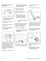
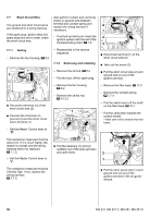
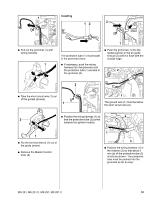
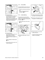
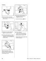
7.7.3 Ground Wire 1 3 Test and install the ground wire as described for the short circuit wire. 1 - Check for contact and continuity 2 and 2 replace the wiring harness if necessary, b 7.7 2310RA148 TG 2310RA151 TG : Use punch-down tool 5910 890 4000 to press the short circuit wire (1) into the guides (arrows) so that the marking (2) is at the edge of the guide and the protective tube (3) locates below the guide rib. 7.7.4 Contact Spring The ground wire must be firmly seated in the contact spring's loop, perform contact and continuity test if necessary, b 7.7.1. - Pull the filter base off the studs, b 12.3 : Lift the contact spring (1) a little and ease it over the tab (arrow). : Ease the contact spring (1) out of the guides in the filter base (2). 2310RA149 TG 2310RA150 TG 2310RA423 TG 1 1 2 : Use punch-down tool 5910 890 4000 to press the ground wire (1) into the guides (arrows) so that the marking (2) is at the edge of the guide. : Swing the filter base (1) to one side. - Check operation of switch lever, b 10.1 - Reassemble all other parts in the reverse sequence. 1 2 : Push the sleeve (1) out of the contact spring (2). - Check the contact spring and replace it if necessary, MS 231, MS 231 C, MS 251, MS 251 C 53
-
 1
1 -
2
-
3
-
4
-
5
-
6
-
7
-
8
-
9
-
10
-
11
-
12
-
13
-
14
-
15
-
16
-
17
-
18
-
19
-
20
-
21
-
22
-
23
-
24
-
25
-
26
-
27
-
28
-
29
-
30
-
31
-
32
-
33
-
34
-
35
-
36
-
37
-
38
-
39
-
40
-
41
-
42
-
43
-
44
-
45
-
46
-
47
-
48
-
 49
49 -
 50
50 -
 51
51 -
 52
52 -
 53
53 -
 54
54 -
 55
55 -
 56
56 -
 57
57 -
 58
58 -
 59
59 -
60
-
61
-
62
-
63
-
64
-
65
-
66
-
67
-
68
-
69
-
70
-
71
-
72
-
73
-
74
-
75
-
76
-
77
-
78
-
79
-
80
-
81
-
82
-
83
-
84
-
85
-
86
-
87
-
88
-
89
-
90
-
91
-
92
-
93
-
94
-
95
-
96
-
97
-
98
-
99
-
100
-
101
-
102
-
103
-
104
-
105
-
106
-
107
-
108
-
109
-
110
-
111
-
112
-
113
-
114
 |
 |
