Stihl MS 251 Instruction Manual - Page 29
Disassembling the brake cable, and retainer, Installing, of the fuel hose 3 and fuel
 |
View all Stihl MS 251 manuals
Add to My Manuals
Save this manual to your list of manuals |
Page 29 highlights
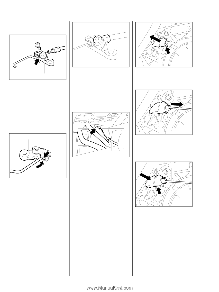
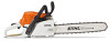
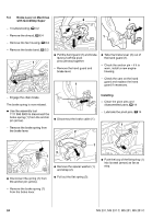
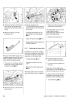
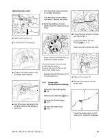
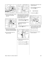
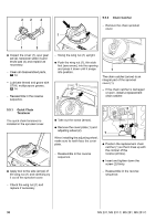
Disassembling the brake cable and retainer 2 1 21 2310RA064 TG 2310RA056 TG 2310RA054 TG 3 4 : Loosen the clamp screw (1) and take out the adjusting screw (2). : Turn the hook (3) so that its offset is next to the recess (arrow) and then remove it from the retainer (4). : Fit the adjusting screw (1) and wind it home until the gap between the screw's hexagon and the retainer is 2 mm. : Fit the clamp screw (2) and tighten it down firmly. 1 : Pry the insert (1) out of the recess (arrow). 2310RA061 TG Installing 2 2 4 21 : Push the brake cable 3 grommet (1) into the insert (2) as far as stop. 1 2310RA058 TG 2310RA065 TG 1 : Position the hook (1) so that it is next to the retainer (2) and push it into the bore (arrow). : Turn the hook (1) slightly while pushing it through the retainer (2). 2310RA055 TG : Pass the brake cable (1) between the tank housing and engine housing to the right of the fuel hose (3) or, on versions with a manual fuel pump, to the right of the fuel hose (3) and fuel return hose (2). : Push the brake cable (1), short hook (4) first, through the bore (arrow) in the engine housing. 1 2 : Push the insert (1) with brake cable (2) into its seat (arrow) as far as stop. - The insert must be flush with the housing ribs. 28 MS 231, MS 231 C, MS 251, MS 251 C
-
 1
1 -
2
-
3
-
4
-
5
-
6
-
7
-
8
-
9
-
10
-
11
-
12
-
13
-
14
-
15
-
16
-
17
-
18
-
19
-
20
-
21
-
22
-
23
-
 24
24 -
 25
25 -
 26
26 -
 27
27 -
 28
28 -
 29
29 -
 30
30 -
 31
31 -
 32
32 -
 33
33 -
 34
34 -
35
-
36
-
37
-
38
-
39
-
40
-
41
-
42
-
43
-
44
-
45
-
46
-
47
-
48
-
49
-
50
-
51
-
52
-
53
-
54
-
55
-
56
-
57
-
58
-
59
-
60
-
61
-
62
-
63
-
64
-
65
-
66
-
67
-
68
-
69
-
70
-
71
-
72
-
73
-
74
-
75
-
76
-
77
-
78
-
79
-
80
-
81
-
82
-
83
-
84
-
85
-
86
-
87
-
88
-
89
-
90
-
91
-
92
-
93
-
94
-
95
-
96
-
97
-
98
-
99
-
100
-
101
-
102
-
103
-
104
-
105
-
106
-
107
-
108
-
109
-
110
-
111
-
112
-
113
-
114
 |
 |