Stihl MS 251 Instruction Manual - Page 83
project fully on the other side of, the buffer.
 |
View all Stihl MS 251 manuals
Add to My Manuals
Save this manual to your list of manuals |
Page 83 highlights
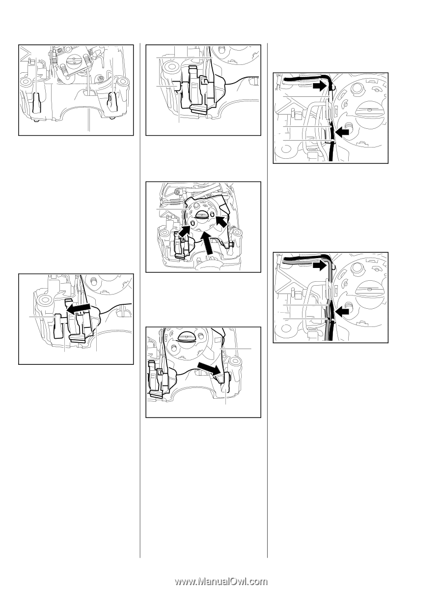
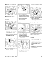
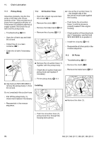
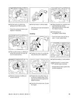
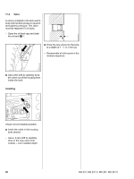
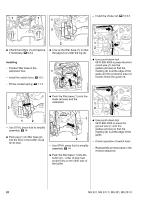
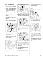
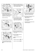
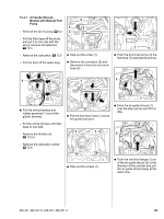
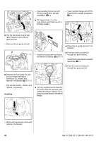
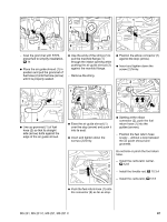
1 1 1 3 - Install the choke rod, b 10.3.3 3 2310RA316 TG 2310RA314 TG 2310RA148 TG 2 1 2 : Check the buffers (1) and replace : Line up the filter base (1) so that if necessary, b 9.3.2 the peg (2) is under the lug (3). Installing - Position filter base in the carburetor box. 1 - Install the switch lever, b 10.1 : Use punch-down tool 5910 890 4000 to press the short circuit wire (1) into the guides (arrows) so that the marking (2) is at the edge of the guide and the protective tube (3) locates below the guide rib. - Fit the contact spring, b 7.7.4 2310RA317 TG : Push the filter base (1) onto the studs (arrows) and the carburetor. 1 3 2 2310RA149 TG 2310RA315 TG 1 2 - Use STIHL press fluid to simplify assembly, b 14 : Push peg (1) on filter base (2) into the bore in the buffer (3) as far as stop. 1 2 - Use STIHL press fluid to simplify assembly, b 14 : Push the filter base (1) into the buffer (2) - collar of peg must project fully on the other side of the buffer. 2310RA318 TG : Use punch-down tool 5910 890 4000 to press the ground wire (1) into the guides (arrows) so that the marking (2) is at the edge of the guide. - Check operation of switch lever. - Reassemble all other parts in the reverse sequence. 82 MS 231, MS 231 C, MS 251, MS 251 C
-
 1
1 -
2
-
3
-
4
-
5
-
6
-
7
-
8
-
9
-
10
-
11
-
12
-
13
-
14
-
15
-
16
-
17
-
18
-
19
-
20
-
21
-
22
-
23
-
24
-
25
-
26
-
27
-
28
-
29
-
30
-
31
-
32
-
33
-
34
-
35
-
36
-
37
-
38
-
39
-
40
-
41
-
42
-
43
-
44
-
45
-
46
-
47
-
48
-
49
-
50
-
51
-
52
-
53
-
54
-
55
-
56
-
57
-
58
-
59
-
60
-
61
-
62
-
63
-
64
-
65
-
66
-
67
-
68
-
69
-
70
-
71
-
72
-
73
-
74
-
75
-
76
-
77
-
 78
78 -
 79
79 -
 80
80 -
 81
81 -
 82
82 -
 83
83 -
 84
84 -
 85
85 -
 86
86 -
 87
87 -
 88
88 -
89
-
90
-
91
-
92
-
93
-
94
-
95
-
96
-
97
-
98
-
99
-
100
-
101
-
102
-
103
-
104
-
105
-
106
-
107
-
108
-
109
-
110
-
111
-
112
-
113
-
114
 |
 |