Stihl MS 251 Instruction Manual - Page 46
Ignition System, 7.1 Ignition Timing, 7.2 Preseparator, 7.3 Install new ignition module
 |
View all Stihl MS 251 manuals
Add to My Manuals
Save this manual to your list of manuals |
Page 46 highlights
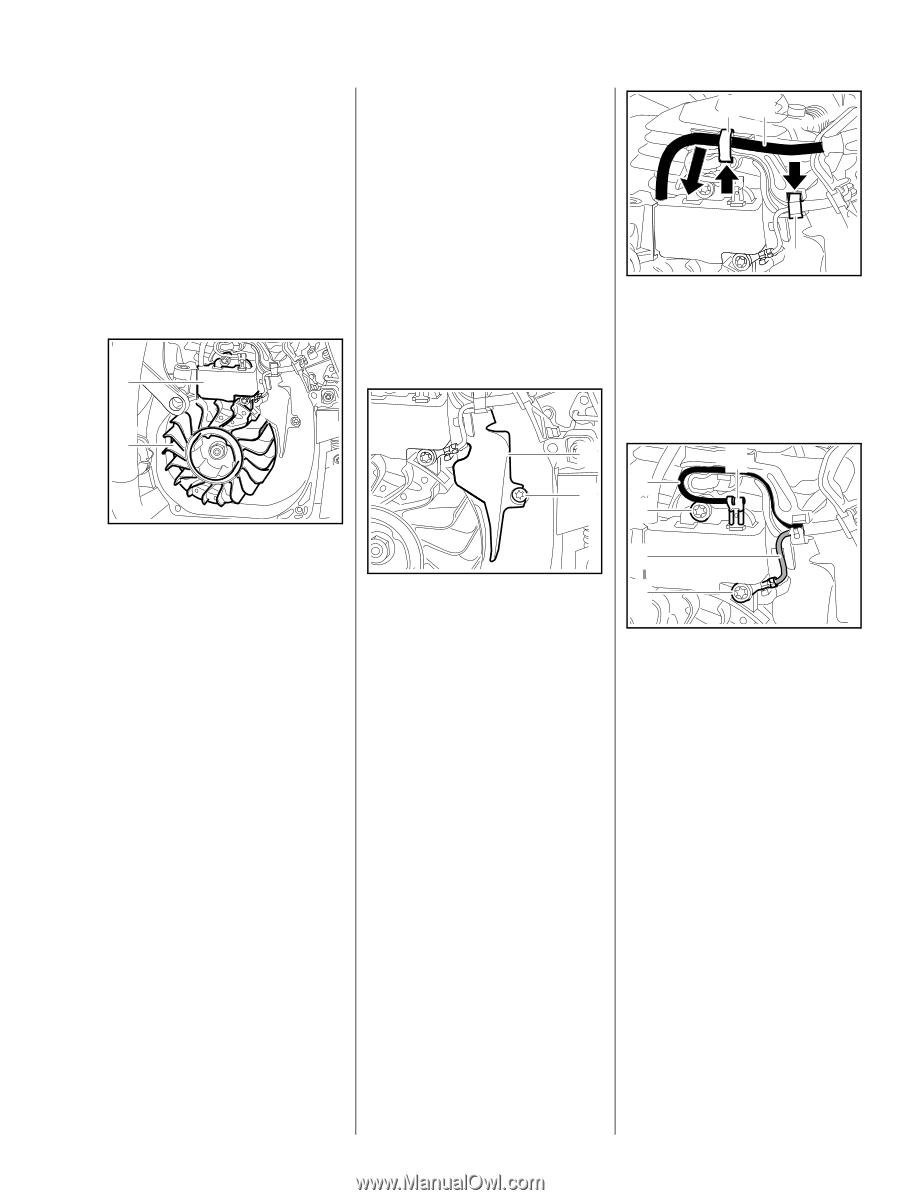
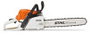
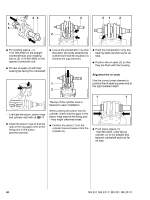
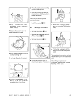
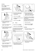
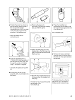
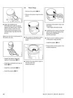
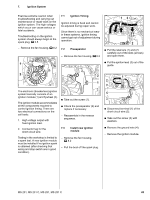
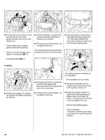
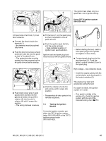
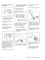
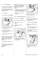
7. Ignition System Exercise extreme caution when troubleshooting and carrying out maintenance or repair work on the ignition system. The high voltages which occur can cause serious or fatal accidents. Troubleshooting on the ignition system should always begin at the spark plug, b 3.5 - Remove the fan housing, b 8.2 1 7.1 Ignition Timing Ignition timing is fixed and cannot be adjusted during repair work. Since there is no mechanical wear in these systems, ignition timing cannot get out of adjustment during operation. 7.2 Preseparator - Remove the fan housing, b 8.2 13 2 : Pull the retainers (1) and (2) carefully out of the slots (arrows) and open them. : Pull the ignition lead (3) out of the guide. 2310RA115 TG 2310RA116 TG 2310RA113 TG 2 2 1 The electronic (breakerless) ignition system basically consists of an ignition module (1) and flywheel (2). The ignition module accommodates all the components required to control ignition timing. There are two electrical connections on the coil body: 1. High voltage output with fixed ignition lead. 2. Connector tag for the short circuit wire. : Take out the screw (1). : Check the preseparator (2) and replace if necessary - Reassemble in the reverse sequence. 7.3 Install new ignition module Testing in the workshop is limited to a spark test. A new ignition module must be installed if no ignition spark is obtained (after checking that wiring and stop switch are in good condition). - Remove the fan housing, b 8.2 - Pull the boot off the spark plug. 2310RA114 TG 1 2 3 4 3 : Disconnect terminal (1) of the short circuit wire (2). : Take out the screw (3) with washers. : Remove the ground wire (4). - Remove the ignition module. MS 231, MS 231 C, MS 251, MS 251 C 45
-
 1
1 -
2
-
3
-
4
-
5
-
6
-
7
-
8
-
9
-
10
-
11
-
12
-
13
-
14
-
15
-
16
-
17
-
18
-
19
-
20
-
21
-
22
-
23
-
24
-
25
-
26
-
27
-
28
-
29
-
30
-
31
-
32
-
33
-
34
-
35
-
36
-
37
-
38
-
39
-
40
-
 41
41 -
 42
42 -
 43
43 -
 44
44 -
 45
45 -
 46
46 -
 47
47 -
 48
48 -
 49
49 -
 50
50 -
 51
51 -
52
-
53
-
54
-
55
-
56
-
57
-
58
-
59
-
60
-
61
-
62
-
63
-
64
-
65
-
66
-
67
-
68
-
69
-
70
-
71
-
72
-
73
-
74
-
75
-
76
-
77
-
78
-
79
-
80
-
81
-
82
-
83
-
84
-
85
-
86
-
87
-
88
-
89
-
90
-
91
-
92
-
93
-
94
-
95
-
96
-
97
-
98
-
99
-
100
-
101
-
102
-
103
-
104
-
105
-
106
-
107
-
108
-
109
-
110
-
111
-
112
-
113
-
114
 |
 |