Stihl MS 251 Instruction Manual - Page 71
Insert the screws and tighten, locates in the tank housing seat.
 |
View all Stihl MS 251 manuals
Add to My Manuals
Save this manual to your list of manuals |
Page 71 highlights
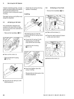
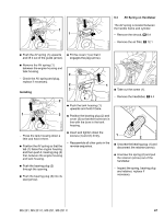
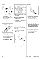
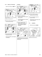
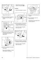
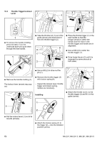
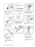
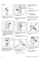
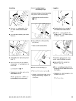
- Inspect the AV spring and replace if necessary, b 9.3 2 1 Installing 2 1 - Place the handlebar in position. 2310RA246 TG 2310RA156 TG 1 - Take out the screws (1). : Ease the handlebar (2) sideways 2 and take it out of the guide (arrow). 1 : Place plug (1) of AV spring on the cylinder. : Insert and tighten down the screw (2) firmly. 2310RA158 TG 1 1 2 : Lift the handlebar (1), lug (2) first, into the recess (arrow) until it locates in the tank housing seat. - Reassemble all other parts in the reverse sequence. - Insert the screws and tighten them down firmly. 2310RA157 TG : Remove the screws (1) from the underside of the machine and lift 1 the handlebar (2) out of its seat (arrow). 2310RA159 TG 0001RA232 TG 1 : Ease the handlebar (1) sideways and place it in the guide (arrow). - Insert the screws and tighten them down firmly. : Push the handlebar (1) out of the lower guide. - Remove the handlebar (1), check it and replace if necessary. 70 MS 231, MS 231 C, MS 251, MS 251 C
-
 1
1 -
2
-
3
-
4
-
5
-
6
-
7
-
8
-
9
-
10
-
11
-
12
-
13
-
14
-
15
-
16
-
17
-
18
-
19
-
20
-
21
-
22
-
23
-
24
-
25
-
26
-
27
-
28
-
29
-
30
-
31
-
32
-
33
-
34
-
35
-
36
-
37
-
38
-
39
-
40
-
41
-
42
-
43
-
44
-
45
-
46
-
47
-
48
-
49
-
50
-
51
-
52
-
53
-
54
-
55
-
56
-
57
-
58
-
59
-
60
-
61
-
62
-
63
-
64
-
65
-
 66
66 -
 67
67 -
 68
68 -
 69
69 -
 70
70 -
 71
71 -
 72
72 -
 73
73 -
 74
74 -
 75
75 -
 76
76 -
77
-
78
-
79
-
80
-
81
-
82
-
83
-
84
-
85
-
86
-
87
-
88
-
89
-
90
-
91
-
92
-
93
-
94
-
95
-
96
-
97
-
98
-
99
-
100
-
101
-
102
-
103
-
104
-
105
-
106
-
107
-
108
-
109
-
110
-
111
-
112
-
113
-
114
 |
 |
