Stihl MS 251 Instruction Manual - Page 44
The inner pin, must point towards
 |
View all Stihl MS 251 manuals
Add to My Manuals
Save this manual to your list of manuals |
Page 44 highlights
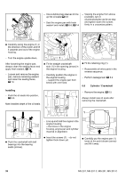
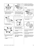
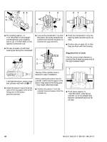
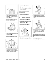
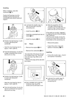
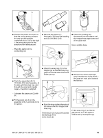
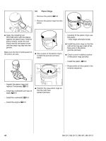
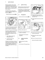
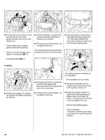
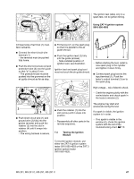
1 5904RA091 TG 5904RA089 TG 2710RA124 TG 2 1 : Position the piston as shown so that the arrow (arrow) points to the rear and the straight crankshaft stub (1) is on the right - the arrow must point in the direction of the exhaust port. : Remove the sleeve (1) 5910 893 1707 from the installing tool (2) 5910 890 2210. : Press the installing tool downwards into the sleeve until the magnet butts against the end of the guide slot. Use a suitable base. - Place the piston on the connecting rod. 1 165RA153 TG 21 216RA178 TG 2 : Push the assembly drift (1) 1110 893 4700 into the piston, at the side with the snap ring, and through the small end (needle cage) - the piston is aligned. 2310RA426 TG : Attach the snap ring (1) to the magnet (2) so that the snap ring gap is on the flat side of the tool's shank (arrow). 21 : Remove the sleeve and slip it onto the other end of the shank - the inner pin must point towards the flat face. - Lubricate the piston pin (2) with oil. 5904RA090 TG 2710RA419 TG : Fit the piston pin (2) on the assembly drift (1) and slide it into the piston. : Push the large slotted diameter of the sleeve over the magnet and snap ring. The inner pin (1) must point towards the flat face of the tool's shank (2). 1 Fit the snap ring (1) so that its gap (arrow) is on the piston's vertical axis (it must point up). MS 231, MS 231 C, MS 251, MS 251 C 43
-
 1
1 -
2
-
3
-
4
-
5
-
6
-
7
-
8
-
9
-
10
-
11
-
12
-
13
-
14
-
15
-
16
-
17
-
18
-
19
-
20
-
21
-
22
-
23
-
24
-
25
-
26
-
27
-
28
-
29
-
30
-
31
-
32
-
33
-
34
-
35
-
36
-
37
-
38
-
 39
39 -
 40
40 -
 41
41 -
 42
42 -
 43
43 -
 44
44 -
 45
45 -
 46
46 -
 47
47 -
 48
48 -
 49
49 -
50
-
51
-
52
-
53
-
54
-
55
-
56
-
57
-
58
-
59
-
60
-
61
-
62
-
63
-
64
-
65
-
66
-
67
-
68
-
69
-
70
-
71
-
72
-
73
-
74
-
75
-
76
-
77
-
78
-
79
-
80
-
81
-
82
-
83
-
84
-
85
-
86
-
87
-
88
-
89
-
90
-
91
-
92
-
93
-
94
-
95
-
96
-
97
-
98
-
99
-
100
-
101
-
102
-
103
-
104
-
105
-
106
-
107
-
108
-
109
-
110
-
111
-
112
-
113
-
114
 |
 |
