Stihl MS 251 Instruction Manual - Page 22
Brake Lever, Carry out the other checks - c parts
 |
View all Stihl MS 251 manuals
Add to My Manuals
Save this manual to your list of manuals |
Page 22 highlights
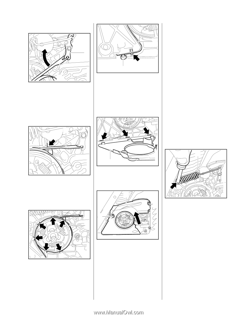
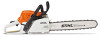
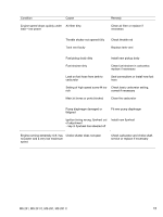
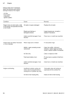
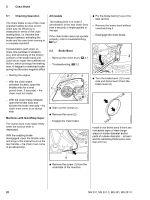
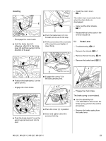
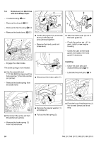
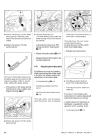
Installing - Install the clutch drum, b 4.1 2 OP 1 - Disengage the chain brake : Hold the brake band (1) sideways, attach it to the brake lever (2) and then swing it in the direction of its seat. 2310RA009 TG 2310RA012 TG 1 The clutch drum must rotate freely when the chain brake is disengaged. 2 : Push the brake band (1) into its seat (arrow) as far as stop. - Carry out the other checks, b 5.1 - Reassemble all other parts in the reverse sequence. : Fit the screw (2) on the underside of the machine and tighten it down firmly. 5.3 Brake Lever - Troubleshooting, b 3.2 - Remove the shroud, b 6.4 - Remove the fan housing, b 8.2 1 - Remove the brake band, b 5.2 2310RA013 TG 2310RA010 TG TOP 1 : Position the brake band (1) in the guide (arrow). : Engage the cover (1) in the slots (arrows) first. - Engage the chain brake. 1 2 TOP 2 TOP 1 2310RA011 TG : Place the cover (1) in position. : Push the brake band (1) over the guide lugs (arrows) and into its seat. : Insert and tighten down the screws (2) firmly. 2310RA014 TG 1 TOP - Engage the chain brake. The brake spring is now relaxed. : Use the assembly tool 1117 890 0900 to disconnect the brake spring (1) from the anchor pin (arrow). - Remove the brake spring from the brake lever. 2310RA015 TG MS 231, MS 231 C, MS 251, MS 251 C 21
-
 1
1 -
2
-
3
-
4
-
5
-
6
-
7
-
8
-
9
-
10
-
11
-
12
-
13
-
14
-
15
-
16
-
 17
17 -
 18
18 -
 19
19 -
 20
20 -
 21
21 -
 22
22 -
 23
23 -
 24
24 -
 25
25 -
 26
26 -
 27
27 -
28
-
29
-
30
-
31
-
32
-
33
-
34
-
35
-
36
-
37
-
38
-
39
-
40
-
41
-
42
-
43
-
44
-
45
-
46
-
47
-
48
-
49
-
50
-
51
-
52
-
53
-
54
-
55
-
56
-
57
-
58
-
59
-
60
-
61
-
62
-
63
-
64
-
65
-
66
-
67
-
68
-
69
-
70
-
71
-
72
-
73
-
74
-
75
-
76
-
77
-
78
-
79
-
80
-
81
-
82
-
83
-
84
-
85
-
86
-
87
-
88
-
89
-
90
-
91
-
92
-
93
-
94
-
95
-
96
-
97
-
98
-
99
-
100
-
101
-
102
-
103
-
104
-
105
-
106
-
107
-
108
-
109
-
110
-
111
-
112
-
113
-
114
 |
 |