Stihl MS 251 Instruction Manual - Page 75
Switch Lever QuickStop Super, Push down the handle
 |
View all Stihl MS 251 manuals
Add to My Manuals
Save this manual to your list of manuals |
Page 75 highlights
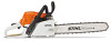
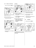
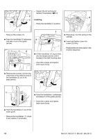
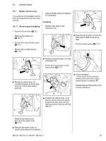
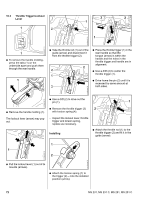
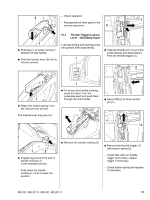
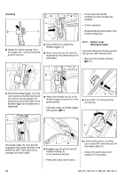
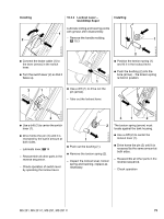
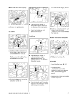
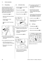
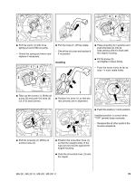
Installing 2 31 1 - Push down the handle 2 molding (1) until it snaps into position. - Check operation - Reassemble all other parts in the reverse sequence. 2310RA182 TG 2310RA179 TG : Attach the torsion spring (1) to the trigger (2) - note the installed position (arrow). : Use a drift (2) to center the throttle trigger (1). : Drive home the pin (3) until it is recessed by the same amount at both sides. 10.3.1 Switch Lever QuickStop Super Lubricate sliding and bearing points with grease after disassembly. - Remove the handle molding, b 10.3 1 1 2 2310RA184 TG 2310RA183 TG 2310RA180 TG : Place the throttle trigger (1) in the rear handle so that the bent leg of the torsion spring engages its seat (arrow) and the holes in the throttle trigger and handle are in alignment. : Attach the throttle rod (1) to the throttle trigger (2) and fit it in the guide (arrow). - Lubricate roller on throttle trigger with grease, b 14 1 : Use a drift (1) to drive out the pin (arrow). 2 1 1 2310RA185 TG 2310RA181 TG 2310RA174 TG The brake cable (1) must be fully engaged in the guide (arrows) or be below the drift - take care not to damage the brake cable. 1 2 : Engage lugs (2) at front end of handle molding (1) in the recesses (arrow). - Press the lockout lever down. : Lift the switch lever (1) a little, turn it about 90° and then pull off the brake cable (2). - Check the switch lever and replace it if necessary 74 MS 231, MS 231 C, MS 251, MS 251 C
-
 1
1 -
2
-
3
-
4
-
5
-
6
-
7
-
8
-
9
-
10
-
11
-
12
-
13
-
14
-
15
-
16
-
17
-
18
-
19
-
20
-
21
-
22
-
23
-
24
-
25
-
26
-
27
-
28
-
29
-
30
-
31
-
32
-
33
-
34
-
35
-
36
-
37
-
38
-
39
-
40
-
41
-
42
-
43
-
44
-
45
-
46
-
47
-
48
-
49
-
50
-
51
-
52
-
53
-
54
-
55
-
56
-
57
-
58
-
59
-
60
-
61
-
62
-
63
-
64
-
65
-
66
-
67
-
68
-
69
-
 70
70 -
 71
71 -
 72
72 -
 73
73 -
 74
74 -
 75
75 -
 76
76 -
 77
77 -
 78
78 -
 79
79 -
 80
80 -
81
-
82
-
83
-
84
-
85
-
86
-
87
-
88
-
89
-
90
-
91
-
92
-
93
-
94
-
95
-
96
-
97
-
98
-
99
-
100
-
101
-
102
-
103
-
104
-
105
-
106
-
107
-
108
-
109
-
110
-
111
-
112
-
113
-
114
 |
 |