Stihl MS 251 Instruction Manual - Page 43
Piston, approx. 150°C 300°F.
 |
View all Stihl MS 251 manuals
Add to My Manuals
Save this manual to your list of manuals |
Page 43 highlights
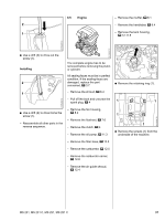
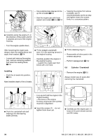
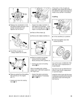
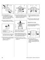
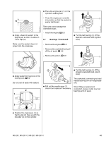
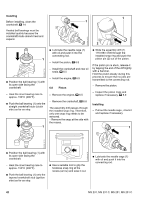
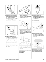
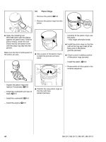
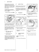
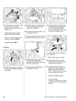
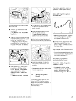
Installing Before installing, clean the crankshaft, b 14 1 1 2710RA117 TG 2710RA119 TG 2310RA425 TG Heated ball bearings must be installed quickly because the crankshaft stubs absorb heat and expand. 2 1 : Position the ball bearing (1) with its open side facing the crankshaft. - Heat the inner bearing race to approx. 150°C (300°F). : Push the ball bearing (1) onto the straight crankshaft stub (clutch side) as far as stop. 1 : Lubricate the needle cage (1) with oil and push it into the connecting rod. - Install the piston, b 6.8 - Install the crankshaft and new oil seals, b 6.5 - Install the engine, b 6.5 6.8 Piston - Remove the engine, b 6.5 - Remove the crankshaft, b 6.6 The assembly drift passes through the installed snap ring. Therefore, only one snap ring needs to be removed. - Remove the snap at the side with the recess. : Slide the assembly drift (1) 1110 893 4700 through the installed snap ring and push the piston pin (2) out of the piston. If the piston pin is stuck, release it by tapping the end of the drift lightly with a hammer. Hold the piston steady during this process to ensure that no jolts are transmitted to the connecting rod. - Remove the piston. - Inspect the piston rings and replace if necessary, b 6.9 Installing - Pull out the needle cage , check it and replace if necessary. 1 2710RA118 TG 2710RA418 TG 2710RA123 TG : Position the ball bearing (1) with its open side facing the crankshaft. - Heat the inner bearing race to approx. 150°C (300°F). : Push the ball bearing (1) onto the tapered crankshaft stub (ignition side) as far as stop. : Use a suitable tool to grip the hookless snap ring at the recess (arrow) and ease it out. : Lubricate the needle cage (1) with oil and push it into the connecting rod. 42 MS 231, MS 231 C, MS 251, MS 251 C
-
 1
1 -
2
-
3
-
4
-
5
-
6
-
7
-
8
-
9
-
10
-
11
-
12
-
13
-
14
-
15
-
16
-
17
-
18
-
19
-
20
-
21
-
22
-
23
-
24
-
25
-
26
-
27
-
28
-
29
-
30
-
31
-
32
-
33
-
34
-
35
-
36
-
37
-
 38
38 -
 39
39 -
 40
40 -
 41
41 -
 42
42 -
 43
43 -
 44
44 -
 45
45 -
 46
46 -
 47
47 -
 48
48 -
49
-
50
-
51
-
52
-
53
-
54
-
55
-
56
-
57
-
58
-
59
-
60
-
61
-
62
-
63
-
64
-
65
-
66
-
67
-
68
-
69
-
70
-
71
-
72
-
73
-
74
-
75
-
76
-
77
-
78
-
79
-
80
-
81
-
82
-
83
-
84
-
85
-
86
-
87
-
88
-
89
-
90
-
91
-
92
-
93
-
94
-
95
-
96
-
97
-
98
-
99
-
100
-
101
-
102
-
103
-
104
-
105
-
106
-
107
-
108
-
109
-
110
-
111
-
112
-
113
-
114
 |
 |
