Stihl MS 251 Instruction Manual - Page 72
Control Levers, 10.1 Master Control Lever, 10.1.1 Removing and Installing
 |
View all Stihl MS 251 manuals
Add to My Manuals
Save this manual to your list of manuals |
Page 72 highlights
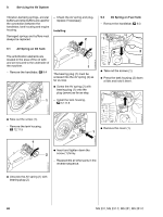
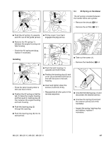
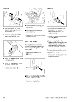
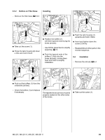
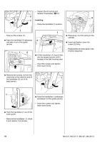
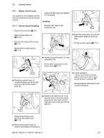
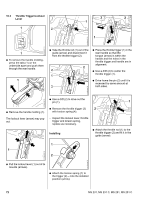
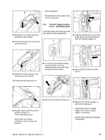
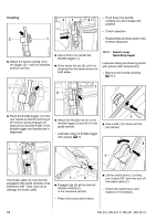
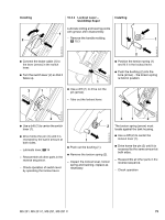
10. Control Levers 10.1 Master Control Lever - Check the filter base and replace 2 The positions of the Master Control it if necessary lever are described in the instruction manual. Installing 1 10.1.1 Removing and Installing - Remove the air filter, b 12.1 - Position filter base in the carburetor box. - Remove the choke rod, b 10.3.3 - Pull the filter base off the studs, b 12.3 : Push the switch lever (1) onto the filter base's shaft (2) as far as stop. - Fit the contact spring, b 7.7.4 2310RA164 TG - Remove the contact spring, b 7.7.4 1 2310RA162 TG 2 : Position the switch lever (1) in the carburetor box. - Fit the short circuit wire on the 1 switch lever, b 7.7.2 2310RA155 TG 2310RA160 TG : Rotate the switch lever (1) counterclockwise as far as stop and pull it off the filter base's shaft (2). 1 : Check operation - short circuit wire's terminal sleeve must touch the contact spring (arrow) in position "0". - Reassemble all other parts in the reverse sequence. 2310RA163 TG 2 : Position the switch lever (1) so that the short circuit wire points towards the filter base and the opening (arrow) lines up with the web (2). 1 2310RA161 TG - Remove the short circuit wire from the switch lever, b 7.7.2 : Remove the switch lever (1), check it and replace if necessary. MS 231, MS 231 C, MS 251, MS 251 C 71
-
 1
1 -
2
-
3
-
4
-
5
-
6
-
7
-
8
-
9
-
10
-
11
-
12
-
13
-
14
-
15
-
16
-
17
-
18
-
19
-
20
-
21
-
22
-
23
-
24
-
25
-
26
-
27
-
28
-
29
-
30
-
31
-
32
-
33
-
34
-
35
-
36
-
37
-
38
-
39
-
40
-
41
-
42
-
43
-
44
-
45
-
46
-
47
-
48
-
49
-
50
-
51
-
52
-
53
-
54
-
55
-
56
-
57
-
58
-
59
-
60
-
61
-
62
-
63
-
64
-
65
-
66
-
 67
67 -
 68
68 -
 69
69 -
 70
70 -
 71
71 -
 72
72 -
 73
73 -
 74
74 -
 75
75 -
 76
76 -
 77
77 -
78
-
79
-
80
-
81
-
82
-
83
-
84
-
85
-
86
-
87
-
88
-
89
-
90
-
91
-
92
-
93
-
94
-
95
-
96
-
97
-
98
-
99
-
100
-
101
-
102
-
103
-
104
-
105
-
106
-
107
-
108
-
109
-
110
-
111
-
112
-
113
-
114
 |
 |
