Cisco 7941G Administration Guide - Page 276
Cable Specifications - cp headset
 |
UPC - 746320949420
View all Cisco 7941G manuals
Add to My Manuals
Save this manual to your list of manuals |
Page 276 highlights
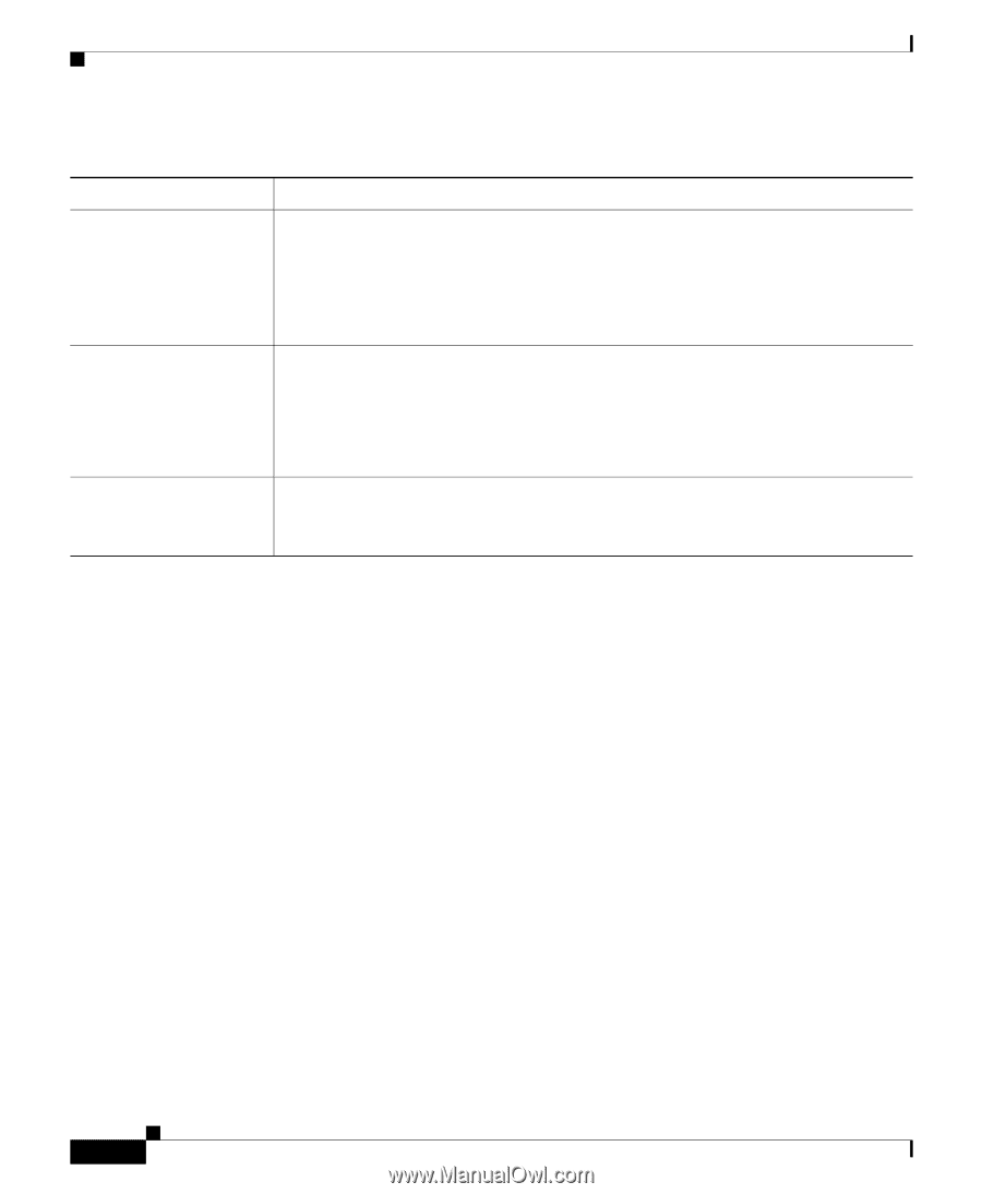
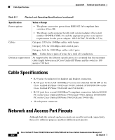
Cable Specifications Appendix D Technical Specifications Table D-1 Physical and Operating Specifications (continued) Specification Value or Range Power options • The phone can receive power from IEEE 802.3af-compliant data switches (Class III) • The phone can be powered locally with a power adapter (Cisco part number CP-PWR-CUBE-3=) and the appropriate power cord (power requirements for the power adapter: 100-240 VAC, 50-60 Hz, 0.5 A) Cables Category 3/5/5e for 10-Mbps cables with 4 pairs Category 5/5e for 100-Mbps cables with 4 pairs Category 5e/6 for 1000-Mbps cables with 4 pairs Note Cables have 4 pairs of wires for a total of 8 conductors. Distance requirements As supported by the Ethernet specification, it is assumed that the maximum cable length between each Cisco Unified IP Phone and the switch is 100 meters (330 feet). Cable Specifications • RJ-9 jack (4-conductor) for handset and headset connection. • RJ-45 jack for the LAN 10/100BaseT connection (labeled 10/100 SW on the Cisco Unified IP Phone 7961G and 7941G; labeled 10/100/1000 SW on the Cisco Unified IP Phone 7961G-GE and 7941G-GE). • RJ-45 jack for a second 10/100BaseT compliant connection (labeled 10/100 PC on the Cisco Unified IP Phone 7961G and 7941G; labeled 10/100/1000 PC on the Cisco Unified IP Phone 7961G-GE and 7941G-GE). • 48-volt power connector. Network and Access Port Pinouts Although both the network and access ports are used for network connectivity, they serve different purposes and have different port pinouts. Cisco Unified IP Phone 7961G/7961G-GE and 7941G/7941G-GE for Cisco Unified Communications Manager 6.1 D-2 OL-14620-01
-
 1
1 -
2
-
3
-
4
-
5
-
6
-
7
-
8
-
9
-
10
-
11
-
12
-
13
-
14
-
15
-
16
-
17
-
18
-
19
-
20
-
21
-
22
-
23
-
24
-
25
-
26
-
27
-
28
-
29
-
30
-
31
-
32
-
33
-
34
-
35
-
36
-
37
-
38
-
39
-
40
-
41
-
42
-
43
-
44
-
45
-
46
-
47
-
48
-
49
-
50
-
51
-
52
-
53
-
54
-
55
-
56
-
57
-
58
-
59
-
60
-
61
-
62
-
63
-
64
-
65
-
66
-
67
-
68
-
69
-
70
-
71
-
72
-
73
-
74
-
75
-
76
-
77
-
78
-
79
-
80
-
81
-
82
-
83
-
84
-
85
-
86
-
87
-
88
-
89
-
90
-
91
-
92
-
93
-
94
-
95
-
96
-
97
-
98
-
99
-
100
-
101
-
102
-
103
-
104
-
105
-
106
-
107
-
108
-
109
-
110
-
111
-
112
-
113
-
114
-
115
-
116
-
117
-
118
-
119
-
120
-
121
-
122
-
123
-
124
-
125
-
126
-
127
-
128
-
129
-
130
-
131
-
132
-
133
-
134
-
135
-
136
-
137
-
138
-
139
-
140
-
141
-
142
-
143
-
144
-
145
-
146
-
147
-
148
-
149
-
150
-
151
-
152
-
153
-
154
-
155
-
156
-
157
-
158
-
159
-
160
-
161
-
162
-
163
-
164
-
165
-
166
-
167
-
168
-
169
-
170
-
171
-
172
-
173
-
174
-
175
-
176
-
177
-
178
-
179
-
180
-
181
-
182
-
183
-
184
-
185
-
186
-
187
-
188
-
189
-
190
-
191
-
192
-
193
-
194
-
195
-
196
-
197
-
198
-
199
-
200
-
201
-
202
-
203
-
204
-
205
-
206
-
207
-
208
-
209
-
210
-
211
-
212
-
213
-
214
-
215
-
216
-
217
-
218
-
219
-
220
-
221
-
222
-
223
-
224
-
225
-
226
-
227
-
228
-
229
-
230
-
231
-
232
-
233
-
234
-
235
-
236
-
237
-
238
-
239
-
240
-
241
-
242
-
243
-
244
-
245
-
246
-
247
-
248
-
249
-
250
-
251
-
252
-
253
-
254
-
255
-
256
-
257
-
258
-
259
-
260
-
261
-
262
-
263
-
264
-
265
-
266
-
267
-
268
-
269
-
270
-
 271
271 -
 272
272 -
 273
273 -
 274
274 -
 275
275 -
 276
276 -
 277
277 -
 278
278 -
 279
279 -
 280
280 -
 281
281 -
282
-
283
-
284
-
285
-
286
-
287
-
288
-
289
-
290
-
291
-
292
-
293
-
294
-
295
-
296
-
297
-
298
-
299
-
300
-
301
-
302
 |
 |