Cisco 7941G Administration Guide - Page 64
Understanding the Phone Startup Process - dialplan
 |
UPC - 746320949420
View all Cisco 7941G manuals
Add to My Manuals
Save this manual to your list of manuals |
Page 64 highlights
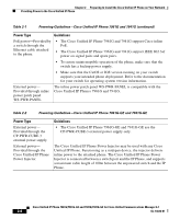
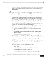
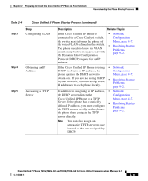
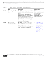
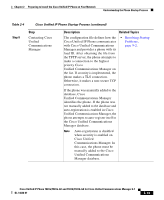
Chapter 2 Preparing to Install the Cisco Unified IP Phone on Your Network Understanding the Phone Startup Process • Dial Plan-.xml • Softkey Template-.xml The filenames are derived from the MAC Address and Description fields in the Phone Configuration window of Cisco Unified Communications Manager Administration. The MAC address uniquely identifies the phone. For more information refer to the Cisco Unified Communications Manager Administration Guide. Understanding the Phone Startup Process When connecting to the VoIP network, the Cisco Unified IP Phone 7961G/7961G-GE and 7941G/7941G-GE go through a standard startup process that is described in Table 2-4. Depending on your specific network configuration, not all of these steps may occur on your Cisco Unified IP Phone. Table 2-4 Cisco Unified IP Phone Startup Process Step 1 Step 2 Step Obtaining Power from the Switch Loading the Stored Phone Image Description Related Topics If a phone is not using external power, the switch provides in-line power through the Ethernet cable attached to the phone. • Adding Phones to the Cisco Unified Communications Manager Database, page 2-14. • Resolving Startup Problems, page 9-2. The Cisco Unified IP Phone has non-volatile Flash memory in which it stores firmware images and user-defined preferences. At startup, the phone runs a bootstrap loader that loads a phone image stored in Flash memory. Using this image, the phone initializes its software and hardware. Resolving Startup Problems, page 9-2. 2-10 Cisco Unified IP Phone 7961G/7961G-GE and 7941G/7941G-GE for Cisco Unified Communications Manager 6.1 OL-14620-01
-
 1
1 -
2
-
3
-
4
-
5
-
6
-
7
-
8
-
9
-
10
-
11
-
12
-
13
-
14
-
15
-
16
-
17
-
18
-
19
-
20
-
21
-
22
-
23
-
24
-
25
-
26
-
27
-
28
-
29
-
30
-
31
-
32
-
33
-
34
-
35
-
36
-
37
-
38
-
39
-
40
-
41
-
42
-
43
-
44
-
45
-
46
-
47
-
48
-
49
-
50
-
51
-
52
-
53
-
54
-
55
-
56
-
57
-
58
-
 59
59 -
 60
60 -
 61
61 -
 62
62 -
 63
63 -
 64
64 -
 65
65 -
 66
66 -
 67
67 -
 68
68 -
 69
69 -
70
-
71
-
72
-
73
-
74
-
75
-
76
-
77
-
78
-
79
-
80
-
81
-
82
-
83
-
84
-
85
-
86
-
87
-
88
-
89
-
90
-
91
-
92
-
93
-
94
-
95
-
96
-
97
-
98
-
99
-
100
-
101
-
102
-
103
-
104
-
105
-
106
-
107
-
108
-
109
-
110
-
111
-
112
-
113
-
114
-
115
-
116
-
117
-
118
-
119
-
120
-
121
-
122
-
123
-
124
-
125
-
126
-
127
-
128
-
129
-
130
-
131
-
132
-
133
-
134
-
135
-
136
-
137
-
138
-
139
-
140
-
141
-
142
-
143
-
144
-
145
-
146
-
147
-
148
-
149
-
150
-
151
-
152
-
153
-
154
-
155
-
156
-
157
-
158
-
159
-
160
-
161
-
162
-
163
-
164
-
165
-
166
-
167
-
168
-
169
-
170
-
171
-
172
-
173
-
174
-
175
-
176
-
177
-
178
-
179
-
180
-
181
-
182
-
183
-
184
-
185
-
186
-
187
-
188
-
189
-
190
-
191
-
192
-
193
-
194
-
195
-
196
-
197
-
198
-
199
-
200
-
201
-
202
-
203
-
204
-
205
-
206
-
207
-
208
-
209
-
210
-
211
-
212
-
213
-
214
-
215
-
216
-
217
-
218
-
219
-
220
-
221
-
222
-
223
-
224
-
225
-
226
-
227
-
228
-
229
-
230
-
231
-
232
-
233
-
234
-
235
-
236
-
237
-
238
-
239
-
240
-
241
-
242
-
243
-
244
-
245
-
246
-
247
-
248
-
249
-
250
-
251
-
252
-
253
-
254
-
255
-
256
-
257
-
258
-
259
-
260
-
261
-
262
-
263
-
264
-
265
-
266
-
267
-
268
-
269
-
270
-
271
-
272
-
273
-
274
-
275
-
276
-
277
-
278
-
279
-
280
-
281
-
282
-
283
-
284
-
285
-
286
-
287
-
288
-
289
-
290
-
291
-
292
-
293
-
294
-
295
-
296
-
297
-
298
-
299
-
300
-
301
-
302
 |
 |