Cisco CSS 11501 Getting Started Guide - Page 30
State Sequence, LED Color, LED State, Table 1-2, Status LEDs Boot Definitions
 |
UPC - 746320761664
View all Cisco CSS 11501 manuals
Add to My Manuals
Save this manual to your list of manuals |
Page 30 highlights
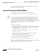
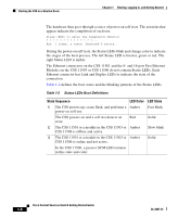
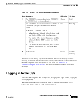
Booting the CSS on a Routine Basis Chapter 1 Booting, Logging In, and Getting Started The hardware then goes through a series of power-on self tests. The asterisks that appear indicate the completion of each test. Press to enter the Diagnostic Monitor Ran 1 times, x tests. Detected 0 errors. During the power-on self tests, the Status LEDs blink and change color to indicate the stages of the boot process. The left Status LED is bicolor, green or red. The right Status LED is amber. The Ethernet connectors on the CSS 11501 and the 8- and 16-port Fast Ethernet Modules on the CSS 11503 or CSS 11506 do not contain Status LEDs. Each Ethernet connector has Link and Duplex LEDs to indicate the state of the connection. Table 1-2 defines the boot states and the blinking patterns of the Status LEDs. Table 1-2 Status LEDs Boot Definitions State Sequence LED Color LED State 1. The CSS powers up, scans flash, and performs a Amber power-on self test. Fast blink The CSS powers on and a self test detects an Red error. Solid 2. The CSS 11501 or a module in the CSS 11503 or Amber CSS 11506 is offline and active. Slow blink 3. The CSS 11501 or a module in the CSS 11503 or Amber CSS 11506 is online and not active. Solid In the CSS 11506, a passive SCM LED remains in this state and color. Cisco Content Services Switch Getting Started Guide 1-8 OL-6037-01
-
 1
1 -
2
-
3
-
4
-
5
-
6
-
7
-
8
-
9
-
10
-
11
-
12
-
13
-
14
-
15
-
16
-
17
-
18
-
19
-
20
-
21
-
22
-
23
-
24
-
 25
25 -
 26
26 -
 27
27 -
 28
28 -
 29
29 -
 30
30 -
 31
31 -
 32
32 -
 33
33 -
 34
34 -
 35
35 -
36
-
37
-
38
-
39
-
40
-
41
-
42
-
43
-
44
-
45
-
46
-
47
-
48
-
49
-
50
-
51
-
52
-
53
-
54
-
55
-
56
-
57
-
58
-
59
-
60
-
61
-
62
-
63
-
64
-
65
-
66
-
67
-
68
-
69
-
70
-
71
-
72
-
73
-
74
-
75
-
76
-
77
-
78
-
79
-
80
-
81
-
82
-
83
-
84
-
85
-
86
-
87
-
88
-
89
-
90
-
91
-
92
-
93
-
94
-
95
-
96
-
97
-
98
-
99
-
100
-
101
-
102
-
103
-
104
-
105
-
106
-
107
-
108
-
109
-
110
-
111
-
112
-
113
-
114
-
115
-
116
-
117
-
118
-
119
-
120
-
121
-
122
-
123
-
124
-
125
-
126
-
127
-
128
-
129
-
130
-
131
-
132
-
133
-
134
-
135
-
136
-
137
-
138
-
139
-
140
-
141
-
142
 |
 |