Dell Inspiron 7000 Dell Inspiron 7000 Service Manual
Dell Inspiron 7000 Manual
 |
View all Dell Inspiron 7000 manuals
Add to My Manuals
Save this manual to your list of manuals |
Dell Inspiron 7000 manual content summary:
- Dell Inspiron 7000 | Dell Inspiron 7000 Service Manual - Page 1
- Dell Inspiron 7000 | Dell Inspiron 7000 Service Manual - Page 2
in any manner whatsoever without the written permission of Dell Computer Corporation is strictly forbidden. Trademarks used in this text: Dell and the DELL logo are registered trademarks and Inspiron is a trademark of Dell Computer Corporation; MS-DOS is a registered trademark of Microsoft - Dell Inspiron 7000 | Dell Inspiron 7000 Service Manual - Page 3
Display 1-3 Battery Charge Gauge 1-4 System Power 1-5 Power Management Mode 1-5 Smart CPU Mode 1-6 Standby Time-Out 1-6 Suspend Time-Out 1-6 Suspend Mode 1-7 Interrupt Assignments 1-7 Technical Specifications 1-8 Initial User Contact 2-1 Visual Inspection 2-2 Observing the Boot Routine - Dell Inspiron 7000 | Dell Inspiron 7000 Service Manual - Page 4
Factory Repair Parts and Assemblies 4-15 Hard-Disk Drive 4-28 Combo Module 4-29 General Disassembly 4-31 Keyboard 4-32 Thermal Shield and Internal Modem 4-34 Display Assembly and Components 4-36 Display Assembly 4-37 Front Bezel 4-38 13.3-Inch LCD Panel 4-39 13.3-Inch LCD Brackets and - Dell Inspiron 7000 | Dell Inspiron 7000 Service Manual - Page 5
or Secondary Battery Removal 4-8 Releasing a ZIF Connector 4-9 Exploded View-Computer 4-10 Exploded View-13.3-Inch Display Assembly 4-11 Exploded View-14.1-Inch Display Assembly 4-12 Exploded View-Palmrest Assembly 4-13 Exploded View-Base Assembly 4-14 Hard-Disk Drive Disassembly 4-28 CD - Dell Inspiron 7000 | Dell Inspiron 7000 Service Manual - Page 6
Table 1-1. Table 1-2. Table 3-1. Table 3-2. Table 4-1. Table 4-2. Interrupt Assignments 1-7 Technical Specifications 1-8 POST Beep Codes 3-2 System Error Messages 3-2 Factory Repair Parts and Assemblies 4-15 Screw Location Template 4-31 viii - Dell Inspiron 7000 | Dell Inspiron 7000 Service Manual - Page 7
ix - Dell Inspiron 7000 | Dell Inspiron 7000 Service Manual - Page 8
to information provided in this manual and the User's Guide that came with the system, Dell provides the Diagnostics and Troubleshooting Guide for troubleshooting procedures and instructions on using the Dell diagnostics to test the computer system. Throughout this manual, there may be blocks of - Dell Inspiron 7000 | Dell Inspiron 7000 Service Manual - Page 9
300 MHz and a 14.1-in. XGA active-matrix TFT LCD. In addition to the standard features found in IBM-compatible portable computers, the Dell Inspiron 7000 computers include the following new and/or advanced features: A minimum of 32 MB of SDRAM on the system board. The memory capacity can be - Dell Inspiron 7000 | Dell Inspiron 7000 Service Manual - Page 10
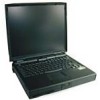
computer speakers. USB devices are hot-pluggable, meaning that they can be connected and disconnected while the system is running. PCI docking connector for full port replication. Kensington Lock, which secures the notebook. Figures 1-1 and 1-2 illustrate front and back views of the Inspiron 7000 - Dell Inspiron 7000 | Dell Inspiron 7000 Service Manual - Page 11
video TV connector docking connector USB connector PS/2 connector infrared port speaker PC Card slots audio jacks (3) AC adapter connector Three status and two on the left side (see Figure 1-4): System power: Solid green light when the system is on; blinking green light when system is in - Dell Inspiron 7000 | Dell Inspiron 7000 Service Manual - Page 12
percent life remaining). The system beeps when this level is first reached. Floppy disk drive activity: Blinking green light as the drive is being accessed. CD-ROM or DVD-ROM drive activity: Blinking green light as the drive is being accessed. system power hard-disk drive activity battery status - Dell Inspiron 7000 | Dell Inspiron 7000 Service Manual - Page 13
management features that remove power from parts of the computer that are not being used. Attach the AC power adapter to the computer, whenever possible, to conserve battery power. When the AC adapter is attached, the battery is charged while the computer uses AC power. The Power Menu of the Setup - Dell Inspiron 7000 | Dell Inspiron 7000 Service Manual - Page 14
the computer remains idle (no I/O activity) before activating standby mode to conserve battery power. computer remains idle (no I/O activity) before activating suspend mode. Settings for this option are Disabled, 5 min., 10 min., 15 min., 20 min., 30 min., 40 min., and 60 min. To increase battery - Dell Inspiron 7000 | Dell Inspiron 7000 Service Manual - Page 15
power to the computer. When you resume normal operation, the same programs will be running and the same files will be open that were loaded before you activated this mode. Use Save-to-disk suspend mode to conserve battery power or to preserve system data by quickly saving it to the hard-disk drive - Dell Inspiron 7000 | Dell Inspiron 7000 Service Manual - Page 16
size . . . . . 68 pins Data width (maximum) . . . . . 32 bits Architecture SDRAM Memory module capacities 32- and 64-MB Standard RAM 32-MB SODIMM (13.3-inch display) 64-MB SODIMM (14.1-inch display) Maximum RAM 192 MB Memory access time/ clock frequency 66 MHz BIOS address F000:0000 1-8 - Dell Inspiron 7000 | Dell Inspiron 7000 Service Manual - Page 17
Monitor PS/2 keyboard/mouse . . . . . Infrared Expansion connector TV-out Audio USB one 9-pin connector; 16550-compatible, 16-byte buffer one 25-hole connector; normal (unidirectional), bidirectional, EPP 1.9, or ECP one 15-hole connector one 6-pin mini-DIN connector one IrDA 1.1 port 240 - Dell Inspiron 7000 | Dell Inspiron 7000 Service Manual - Page 18
memory 4 or 8 MB 100 MHz SGRAM LCD interface 65 MHz LVDS TV support Power consumption 3.9 W Controls brightness can be controlled through key combinations Type active-matrix color (TFT) Dimensions (active area): Height 228.5 mm (8.9 inches) Width 299.5 mm (11.8 inches) Diagonal 358.1 mm (14 - Dell Inspiron 7000 | Dell Inspiron 7000 Service Manual - Page 19
: Thickness Width Height Weight Power: Supply voltage Supply current PS/2-compatible 20 points/mm (500 points/inch) 4.65 mm (0.18 inch) at highest component 64-mm (2.52-inch) sensor-active area 47.0-mm (1.85-inch) rectangle with 0.5-mm (0.02-inch) tabs 15 g (0.52 ounce) ± 0.5 g (0.001 ounce - Dell Inspiron 7000 | Dell Inspiron 7000 Service Manual - Page 20
29.6 mm (1.17 inches) Width 60.0 mm (2.36 inches) Depth 105 mm (4.13 inches) Weight (with cables 0.3 kg (0.66 lb) Temperature range: Operating 5° to 35°C (41° to 95°F) Storage 20° to 50°C (-4° to 122°F) 1 Battery performance features such as charge time, operating time, and life span can vary - Dell Inspiron 7000 | Dell Inspiron 7000 Service Manual - Page 21
Height Width Depth Weight (includes hard-disk drive, diskette drive, and CD-ROM drive 54 mm (2.1 inches) 318 mm (12.52 inches) 254 mm (10 inches) 3.74 kg (8.25 lb) with 13.3-inch display 3.8 kg (8.37 lb) with 14.1-inch display Temperature: Operating 5° to 35°C (41° to 95°F) Storage 20° - Dell Inspiron 7000 | Dell Inspiron 7000 Service Manual - Page 22
1-14 - Dell Inspiron 7000 | Dell Inspiron 7000 Service Manual - Page 23
the appropriate troubleshooting procedure to use. After the user describes the problem, follow these steps: 1. Ask the user to back up any data on the hard-disk drive if the computer's condition permits. See the "Maintaining Your Computer" section of the online System User's Guide. 2. Ask the - Dell Inspiron 7000 | Dell Inspiron 7000 Service Manual - Page 24
light should be on. b. The AC adapter's DC power cable is properly connected to the computer's AC adapter connector. c. The AC adapter and cables are free of any obvious physical damage. 5. If the computer is operating from battery power, remove any installed batteries, verify that they are free of - Dell Inspiron 7000 | Dell Inspiron 7000 Service Manual - Page 25
monitor's controls are set according to the instructions in the docu- mentation for the monitor. 13. If an external mouse is connected, verify the following: a. The mouse is properly connected to the keyboard/keypad/mouse connector on the computer's I/O panel. b. The mouse, its cable, and connectors - Dell Inspiron 7000 | Dell Inspiron 7000 Service Manual - Page 26
when servicing a user's computer. Dell recommends that users make copies of the Dell Diagnostics Diskette. For instructions, see "Before You Start Testing" in Chapter 4, "Running the Dell Diagnostics," of the Dell Inspiron 7000 Reference and Troubleshooting Guide. To observe the boot routine - Dell Inspiron 7000 | Dell Inspiron 7000 Service Manual - Page 27
"Troubleshooting Your Computer," in the Reference and Troubleshooting Guide. If none of the procedures in this chapter reveal the source of the problem or lead to the proper troubleshooting steps for determining the source of the problem, contact Dell for technical assistance. For instructions, see - Dell Inspiron 7000 | Dell Inspiron 7000 Service Manual - Page 28
2-6 - Dell Inspiron 7000 | Dell Inspiron 7000 Service Manual - Page 29
probable causes of the fault in each case. If a faulty computer does not emit beep codes or display problem. See "Running the Dell Diagnostics" found later in this chapter. If the display cannot display error messages during POST, the computer may emit a series of beeps that identifies the problem - Dell Inspiron 7000 | Dell Inspiron 7000 Service Manual - Page 30
the display during the boot routine or during normal computer operation. The CMOS battery does not have enough charge to power the computer. Connector loose or diskette faulty. Extended memory not configured properly or failed at memory address nnnn. CMOS battery completely discharged. Faulty CMOS - Dell Inspiron 7000 | Dell Inspiron 7000 Service Manual - Page 31
Memory failed at RAM address nnnn. Faulty or improperly seated memory module. Faulty main board. The hard-disk drive failed to initialize. Corrupted hard-disk drive boot sector or configuration file. Faulty hard-disk drive. Faulty main board. The hard-disk drive con- Faulty hard-disk drive. - Dell Inspiron 7000 | Dell Inspiron 7000 Service Manual - Page 32
chip on the system board may be malfunctioning. Faulty main board. The Dell Diagnostics contains tests that aid in troubleshooting the computer. The diagnostics diskette contains the following test groups: RAM - Tests the main memory System Set - Tests the primary functions of the main board Video - Dell Inspiron 7000 | Dell Inspiron 7000 Service Manual - Page 33
and Troubleshooting Guide. Follow these steps to start the diagnostics: 1. Install a CD-ROM drive in the options bay. 2. Turn off the computer. 3. Place a copy of the Dell Diagnostics Diskette in the diskette drive, and boot the computer. Starting the diagnostics causes the Dell logo screen to - Dell Inspiron 7000 | Dell Inspiron 7000 Service Manual - Page 34
3-6 - Dell Inspiron 7000 | Dell Inspiron 7000 Service Manual - Page 35
are disconnected from the computer's I/O panel. A part can be replaced or installed by performing the removal procedure in reverse order. When performing the procedures in this chapter that require the computer to be open, use a book or something similar to support the display assembly. The - Dell Inspiron 7000 | Dell Inspiron 7000 Service Manual - Page 36
Small scribe or nylon flat blade Nut driver (5 mm and 5.5 mm) Where applicable, information about screw lengths an antistatic grounding strap to your wrist and to an unpainted metal surface on the computer's I/O panel. If an antistatic grounding strap is not available, periodically discharge static - Dell Inspiron 7000 | Dell Inspiron 7000 Service Manual - Page 37
from the AC adapter and port replicator and removing the main battery, PC Cards, hard-disk drive, memory module cover, video card cover, memory modules, and devices in the options bay. To take these precautionary measures, follow these steps: 1. Determine the power state of the computer. If the - Dell Inspiron 7000 | Dell Inspiron 7000 Service Manual - Page 38
the arrow. Keep holding the latch release with one hand while pulling the battery out of the compartment with the other. latch release bottom of computer latch lock (unlocked position) battery The plastic front bezel on the battery slides back and forth, which allows it to be used in the options - Dell Inspiron 7000 | Dell Inspiron 7000 Service Manual - Page 39
. Loosen the two captive screws that secure the hard-disk drive into the bottom of the computer. The front edge of the cover pops up slightly. Slide the hard-disk drive toward the front of the computer and then lift the drive out of the computer (see Figure 4-7). Removing and Replacing Parts 4-5 - Dell Inspiron 7000 | Dell Inspiron 7000 Service Manual - Page 40
hard-disk drive 8. Remove the video card and memory module covers. Slide the video card cover as far as it will go in the direction of the arrow, and then remove the cover (see Figure 4-8). Remove the memory module cover in the same way. video card cover bottom of computer memory module cover - Dell Inspiron 7000 | Dell Inspiron 7000 Service Manual - Page 41
up slightly. Then pull the memory module out of the socket (see Figure 4-9). bottom of computer metal tabs memory module memory module sockets (2) 10. Remove mm screws (2) video card video card connectors (2) bottom of computer Inspect the two thermal pads on the bottom of the system board - Dell Inspiron 7000 | Dell Inspiron 7000 Service Manual - Page 42
bottom of computer latch release combo module or secondary battery NOTE: If the computer is booted with a diskette drive or secondary battery in pick under the movable part of the connector (see Figure 4-12). For most ZIFs, carefully pry up first one end of the movable part of the connector and - Dell Inspiron 7000 | Dell Inspiron 7000 Service Manual - Page 43
the connector. To reconnect an interface cable to a ZIF connector, follow these steps: 1. Use the flat-blade screwdriver or dental pick to open the movable part of the ZIF connector. 2. Orient the end of the cable with the ZIF connector, and insert the end of the cable into the connector. 3. While - Dell Inspiron 7000 | Dell Inspiron 7000 Service Manual - Page 44
Exploded views of the computer, the 13.3-inch and 14.1-inch display assemblies, the palmrest assembly, and the base assembly are shown in Figures 4-13, 4-14, 4-15, 4-16, and 4-17, respectively. hinge covers (2) display assembly keyboard thermal shield combo module battery hard-disk drive 4-10 - Dell Inspiron 7000 | Dell Inspiron 7000 Service Manual - Page 45
front bezel LCD brackets (2) hinges (2) inverter board LCD panel carrier tray CCFL cable back cover LCD wire harness Removing and Replacing Parts 4-11 - Dell Inspiron 7000 | Dell Inspiron 7000 Service Manual - Page 46
front bezel LCD brackets (2) interposer board hinges (2) inverter board shield inverter board LCD panel carrier tray CCFL cable back cover LCD wire harness 4-12 - Dell Inspiron 7000 | Dell Inspiron 7000 Service Manual - Page 47
IR board palmrest display latch speaker wire harness speakers (2) left speaker cover touch pad button board hard-disk drive heat shield display latch spring touch pad board touch pad bracket right speaker cover Removing and Replacing Parts 4-13 - Dell Inspiron 7000 | Dell Inspiron 7000 Service Manual - Page 48
LVDS board DC-DC board heat exchanger/fan processor board right hinge saddle SODIMM heat sink RJ-11 card system board Kensington lock plastic base 4-14 - Dell Inspiron 7000 | Dell Inspiron 7000 Service Manual - Page 49
Dell does not recommend removal and replacement of these parts in the field. Table 4-1 lists the factory repair parts and assemblies available for the computer. Some parts may only be available as part of a kit or assembly. The subsections in this chapter provide instructions ,M2.5X4.14,5.5HEX,BRS - Dell Inspiron 7000 | Dell Inspiron 7000 Service Manual - Page 50
Latch n/a Spring n/a Left Latch n/a Spring n/a Cover Latch Spring n/a Rubber Feet, Front FOOT,RBR,BTM,NBK,I7000 LED Board CRD,INTFC,LED,NBK,I7000 LED Board Cable CBL,INTFC,LED,NBK,I7000 RJ-11 Cover CVR,SIDE,PLSTC,MDM,I7000 Memory Door DOOR,PLSTC,BTM,RAM,NBK,I7000 VGA Door DOOR - Dell Inspiron 7000 | Dell Inspiron 7000 Service Manual - Page 51
wire SPKR,0.6W,23M,LF,NBK,I7000 Hard-Disk Drive Heat Sink, under Palmrest HTSNK,HD, 13.3" and 14.1" LENS,IR,NBK,I7K LCD Parts for 13.3-Inch 13.3" LCD Panel LCD,TFT,XGA,13.3,I7000,LG Front Bezel BZL,PLSTC,LCD,13.3,NBK,I7000 Display Hinge HNG,MET,LCD,I7000 Display Back Cover CVR,BK,LCD,13 - Dell Inspiron 7000 | Dell Inspiron 7000 Service Manual - Page 52
Right Bracket BRKT,MET,RT,LCD,13.3,I7000 Left Bracket BRKT,MET,LF,LCD,13.3,I7000 LVDS Board CRD,INTFC,LVD,13.3,NBK,LG Right Hinge Cover CVR,HNG,PLSTC,RT,I7000 Left Hinge Cover CVR,HNG,PLSTC,LF,I7000 LCD Parts for 14.1-Inch 14.1" LCD Panel LCD,TFT,XGA,14.1,I7000,LG Front Bezel BZL,PLSTC - Dell Inspiron 7000 | Dell Inspiron 7000 Service Manual - Page 53
bezel SCR,1.7x.35,KSH,MS,CPS Hard-Disk Drive Holder Hard-Disk Drive Cover Assembly ASSY,CARRIER,MTG,HD,NBK,I7000 Plastic Cover CVR,PLSTC,HD,I7000 Top Shield PLT, I7000 Twisted Pair Cable CBL,INTFC,MDM,MTHBD,NBK,I7000 Miscellaneous Parts Modem Kit KIT,CBL,ADPT,MDM,INT,I7000,US Phone - Dell Inspiron 7000 | Dell Inspiron 7000 Service Manual - Page 54
FOOT,RBR,CVR,BTM,14.1,I7000 Lower BMPR,RBR,LWR,LCD,I7000 Upper BMPR,RBR,UPR,LCD,I7000 Customer Kit, 4.0GB Hard-Disk Drive, IBM CUS,HD,4GB,I,IBM,I7K 4.0GB Subassembly Boot Information INFO,1ST BOOT,HARD DRIVE Screw, 3 x .5 SCR,3X.5,KSH,MS,CPS Hard-Disk Drive Carrier Assembly ASSY,CARRIER - Dell Inspiron 7000 | Dell Inspiron 7000 Service Manual - Page 55
IDE,HDD,I7000 Customer Kit, 6.4GB Hard-Disk Drive, IBM CUS,HD,6.4GB,I,12.5MM,IBM,I7K 6.4GB Subassembly Boot Information INFO,1ST BOOT,HARD DRIVE Screw, 3 x 0.5 SCR,M3.0x0.5x4,PHH,NPL Hard-Disk Drive, 6.4GB HD,6.4GB,I,F2,12.5MM,IBM ACDIA Hard-Disk Drive Carrier Assembly ASSY,CARRIER,MTG,HD - Dell Inspiron 7000 | Dell Inspiron 7000 Service Manual - Page 56
,PLSTC,CD,SANYO,I7000 Combo Plastics Kit Plastic Cover CVR,PLSTC,FD,NBK,I7000 CD-ROM/DVD- Memory CUS,DIMM,64M,66M,2K,144,I7000 DIMM, 64MB DIMM,64,66M,8X64,4K,144 Customer Kit, Main Battery CUS,BTRY,MAIN,60W,LIION,I7000 Battery Assembly ASSY,BTRY,60W,LIION,NBK,I7000 60W Lithium Ion Battery - Dell Inspiron 7000 | Dell Inspiron 7000 Service Manual - Page 57
,I7000 Right Plastic Hinge Cover CVR,HNG,PLSTC,RT,I7000 Dell Inspiron Port Replicator (Sierra) Customer Kit, Port Replicator CUS,PPR,I/0,NBK,I7000,US Port Replicator Assembly ASSY,PPR,I/O,NBK,I7000 AC Adaptor ADPT,AC,EXT,19V,70W,NBK,I7000 US Power Cord CORD,PWR,110V,6F,AC ADPT,US Sierra - Dell Inspiron 7000 | Dell Inspiron 7000 Service Manual - Page 58
Dell Inspiron Port Replicator (Sierra) (continued) Left Release Lever LEVER,REL,LF,I/O Lag CARD,LAG Service Manual Service Manual MNL,SERV,I7000,ENG Removal and Replacement Guide DOC,SERV,GDE,I7000,ENG Reference/Troubleshooting Guide GDE,REF/TRBLSHT,I7000,ENG Setup Guide GDE,SETUP,I7000, - Dell Inspiron 7000 | Dell Inspiron 7000 Service Manual - Page 59
,CRYG,LTHR,UNIV,INSP Carrying Case, Leather, Universal CASE,CRYG,LTHR,NBK,UNIVERSAL Labels Regulatory Label LBL,REG,NBK,GNRC,I7000 Label, Intel Inside LBL,INTEL INSIDE,PII,MMX,NBK Regulatory Label, Modem, CAN LBL,REG,MDM,INT,NBK,I7000,CAN Regulatory Label, Battery LBL,REG,BTRY,NBK,I7000 - Dell Inspiron 7000 | Dell Inspiron 7000 Service Manual - Page 60
,NBK,I7K,D266XT,NO BTRY Assembly w/o battery, 266MHz ASSY,NBK,BASE,I7000,13.3,NOBATT 266MHz Field Service Base, no battery, 14.1" BASE,NBK,I7K,D266GT,NO BTRY Assembly w/o battery, 300MHz ASSY,NBK,BASE,I7000,14.1,NOBATT 300MHz Field Service Base, no battery, 14.1" BASE,NBK,I7K,D300GT,NO BTRY - Dell Inspiron 7000 | Dell Inspiron 7000 Service Manual - Page 61
,NBK,BASE,I7000,13.3,OEM Base Assembly, 14.1" ASSY,NBK,BASE,I7000,14.1,OEM Floppy Disk-Drive Assembly ASSY,FD,1.44M,11MM,COMBO,I7000 DVD-ROM Assembly ASSY,DVD,17G,2X,INT,MKE,I7000 Display Assembly, 13.3" ASSY,LCD,XGA,13.3,I7000,LG Display Assembly, 14.1" ASSY,LCD,XGA,14.1,I7000,LG System - Dell Inspiron 7000 | Dell Inspiron 7000 Service Manual - Page 62
a carrier that mounts in the hard-disk drive compartment in the bottom of the computer (see Figure 4-18). Four screws secure the drive inside the carrier. carrier hard-disk drive plastic cover hard-disk drive connector 3-mm screws (4) To remove the hard-disk drive from the carrier, follow these - Dell Inspiron 7000 | Dell Inspiron 7000 Service Manual - Page 63
into the options bay on the left side of the computer. 3-mm screws (6) CD-ROM or DVD-ROM drive bracket flex cable connector side mounting bracket plastic carrier 2.5-mm screws (2) flex cable To remove the CD-ROM drive or DVD-ROM drive from the plastic carrier, follow these steps: 1. Remove the - Dell Inspiron 7000 | Dell Inspiron 7000 Service Manual - Page 64
steps (see Figure 4-19): 1. Remove the two 2.5-mm screws from the side of the CD-ROM/DVD-ROM drive. 2. Remove the side mounting bracket. mounting ear diskette drive metal shielding carrier (bottom) metal shielding carrier (top) flex cable 3-mm screws (5) plastic carrier To remove the diskette - Dell Inspiron 7000 | Dell Inspiron 7000 Service Manual - Page 65
Inspiron 7000 computer contains many screws of various sizes. To help keep track of the screws, use a tackle or pill box as a storage device. Use the location template in Table 4-2 to store the screws during disassembly. Video card (Figure 4-10): 2X K-head, M2x3L Thermal shield (Figure 4-22): Hard - Dell Inspiron 7000 | Dell Inspiron 7000 Service Manual - Page 66
provides the removal procedure for the keyboard. keyboard left hinge cover right hinge cover keyboard cable ZIF connector palmrest assembly 20-mm screws (4) To remove the keyboard, follow these steps (see Figure 4-21): 1. Turn the computer over and remove the four 20-mm screws from the bottom - Dell Inspiron 7000 | Dell Inspiron 7000 Service Manual - Page 67
7. Remove the keyboard from the palmrest assembly. Removing and Replacing Parts 4-33 - Dell Inspiron 7000 | Dell Inspiron 7000 Service Manual - Page 68
that you have removed the keyboard. To remove the thermal shield, follow these steps (see Figure 4-22): 1. Remove the hinge covers. Open the computer to 170 degrees, supporting the display assembly. From the outside edge of the unit, carefully insert a flat-blade screwdriver or scribe into the space - Dell Inspiron 7000 | Dell Inspiron 7000 Service Manual - Page 69
modem card inside) twisted wire pair circular opening 2. If your computer has an internal modem, disconnect the modem flex cable (see the circular opening and pulling the modem carrier box carefully toward the back of the computer (see Figure 4-23). Lift the top off the metal carrier and remove the - Dell Inspiron 7000 | Dell Inspiron 7000 Service Manual - Page 70
This section describes how to remove the display assemblies shown in Figures 4-14 and 4-15 and gives removal and replacement procedures for the components of the display assembly. The display assembly consists of the following components: Front bezel LCD panel - Dell Inspiron 7000 | Dell Inspiron 7000 Service Manual - Page 71
you have removed the keyboard and thermal shield. To remove the display assembly from the computer, follow these steps (see Figure 4-24): 1. Disconnect the LCD wire harness from connector 4. Unlatch the display assembly and lift the assembly off the computer base. Removing and Replacing Parts 4-37 - Dell Inspiron 7000 | Dell Inspiron 7000 Service Manual - Page 72
the removal procedure for the front bezel. 6-mm screws (4) rubber bumpers (2) front bezel rubber screw covers (2) This procedure assumes that you have removed the display assembly from the computer base. To remove the front bezel, follow these steps (see Figure 4-25): 1. Use a dental pick - Dell Inspiron 7000 | Dell Inspiron 7000 Service Manual - Page 73
cover This procedure assumes that you have removed the front bezel. Follow these steps to remove the 13 .3-inch LCD panel (see Figure 4-26): 1. Remove the eight 6-mm screws that secure the left and right LCD brackets to the front plastic cover unit, out of the back cover. Rotate upward from the - Dell Inspiron 7000 | Dell Inspiron 7000 Service Manual - Page 74
remove the inverter board, follow these steps: 1. Remove the 3-mm screw securing the inverter board to the back cover. 2. If you have not removed the LCD panel, disconnect the LCD wire harness from connectors CN1 and CN2 on the inverter board. 3. Remove the inverter board from the back cover. 4-40 - Dell Inspiron 7000 | Dell Inspiron 7000 Service Manual - Page 75
screws from the sides of the mounting brackets. 3. Remove the brackets from the LCD panel. To remove the 13.3-inch LCD panel from the carrier tray, follow these steps: 1. Remove any Kapton tape covering the CCFL cable. 2. Gently pull the cable out of its connector. 3. Remove any Kapton tape from the - Dell Inspiron 7000 | Dell Inspiron 7000 Service Manual - Page 76
interposer board CCFL cable carrier tray hinges (2) inverter board shield 3-mm screw inverter board back cover This procedure assumes that you have removed the front bezel. Follow these steps to remove the 14.1-inch LCD panel (see Figure 4-28): 1. Remove the eight 6-mm screws that secure the - Dell Inspiron 7000 | Dell Inspiron 7000 Service Manual - Page 77
cabling, and detach the LCD wire harness from connector CN1 on the inverter board. 2. Remove any Kapton tape covering the CCFL cable on the back of the LCD. 3. Gently pull the interposer board off the connector to Disconnect the LCD wire harness from the LCD panel. Removing and Replacing Parts 4-43 - Dell Inspiron 7000 | Dell Inspiron 7000 Service Manual - Page 78
This section describes how to remove the palmrest assembly. The palmrest assembly consists of the following components (see Figure 4-16): MPEG-2 card IR board Hard-disk drive heat shield Touch pad assembly Speakers 4-44 - Dell Inspiron 7000 | Dell Inspiron 7000 Service Manual - Page 79
not rock the card to remove it, because this may damage the connectors. 2. Remove the carrier tray by sliding it toward the back of the computer 3. Remove the MPEG-2 card from the carrier tray. Removing and Replacing - Dell Inspiron 7000 | Dell Inspiron 7000 Service Manual - Page 80
LED cable 6-mm screws (4) connector for speaker wire harness base assembly LED connector DC-DC board combo bay 4-mm screws (6) hard-disk drive bay battery bay This procedure assumes that you have removed the keyboard, thermal shield, and display assembly. To remove the palmrest assembly - Dell Inspiron 7000 | Dell Inspiron 7000 Service Manual - Page 81
and move forward around the computer. Carefully lift the palmrest assembly up and pull it forward to unsnap the hidden tabs spaced around the sides and along the top of the battery bay and options bay. When procedures for the components of the palmrest assembly. Removing and Replacing Parts 4-47 - Dell Inspiron 7000 | Dell Inspiron 7000 Service Manual - Page 82
The IR board (see Figure 4-31) controls the power button, lid switch, microphone, and lights on the indicator panel above the keyboard. IR board 4-mm screws (2) IR cable This procedure assumes that you have - Dell Inspiron 7000 | Dell Inspiron 7000 Service Manual - Page 83
from the base assembly. To remove the hard-disk drive heat shield, follow these steps (see Figure 4-32): 1. Place the palmrest assembly face down. 2. Remove the five 4-mm screws securing the hard-disk drive heat shield. 3. Remove the hard-disk drive heat shield. Removing and Replacing Parts 4-49 - Dell Inspiron 7000 | Dell Inspiron 7000 Service Manual - Page 84
cable ZIF connector This procedure assumes that you have removed the palmrest assembly from the base assembly and that you have removed the hard-disk drive heat shield. To remove the touch pad assembly, follow these steps (see Figure 4-33): 1. Remove the three 4-mm screws securing the touch pad - Dell Inspiron 7000 | Dell Inspiron 7000 Service Manual - Page 85
6. Remove the touch pad button board. 7. Remove the four 4-mm screws securing the touch pad bracket. 8. Remove the touch pad bracket. 9. Remove the touch pad. The touch pad buttons are heat-staked into the palmrest assembly and are not removable. Removing and Replacing Parts 4-51 - Dell Inspiron 7000 | Dell Inspiron 7000 Service Manual - Page 86
This procedure assumes that you have removed the palmrest assembly from the base assembly and that you have removed the hard-disk drive heat shield and touch pad assembly. To remove the speakers, follow these steps (see Figure 4-34): 1. Remove any tape securing the speaker cables. 2. Remove the - Dell Inspiron 7000 | Dell Inspiron 7000 Service Manual - Page 87
base assembly consists of the following components: PC Card heat sink Heat exchanger/fan DC-DC board LVDS board RJ-11 card Processor board and memory module Hinge saddles System board PC Card cage Audio board and audio thermal shield Latch assembly Kensington lock Bottom - Dell Inspiron 7000 | Dell Inspiron 7000 Service Manual - Page 88
This section provides the removal procedure for the PC Card heat sink. PC Card heat sink 4-mm screws (2) To remove the PC Card heat sink, follow these steps (see Figure 4-35): 1. Remove the two 4-mm screws securing the PC Card heat sink. 2. Remove the heat sink. 4-54 - Dell Inspiron 7000 | Dell Inspiron 7000 Service Manual - Page 89
from connector JP17 on the system board. 3. Lift the heat exchanger and rotate it upward. 4. Slide the heat exchanger/fan toward the front of the computer until the fan is completely clear of the overhanging palmrest plastic. 5. Lift the heat exchanger/fan out at an angle. 6. Inspect the two thermal - Dell Inspiron 7000 | Dell Inspiron 7000 Service Manual - Page 90
This section provides the removal procedure for the DC-DC board. DC-DC board To remove the DC-DC board, gently pull the DC-DC board off of connectors JP11 and JP16 on the system board (see Figure 4-37). Do not rock the board to remove it, because this may damage the connectors. 4-56 - Dell Inspiron 7000 | Dell Inspiron 7000 Service Manual - Page 91
connectors JP9 and JP8 on the system board. Do not rock the board to remove it, because this may damage the connectors. Removing and Replacing Parts 4-57 - Dell Inspiron 7000 | Dell Inspiron 7000 Service Manual - Page 92
board to remove it, because this may damage the connectors. 3. Lift the SODIMM heat sink off of the memory module. 4. Remove the memory module. Carefully spread the inner metal tabs of the memory module socket to disengage the module from the socket. The module should pop up slightly. Then pull the - Dell Inspiron 7000 | Dell Inspiron 7000 Service Manual - Page 93
5. Inspect the thermal pad beneath the memory module to see if it needs replacement. When reinstalling the SODIMM heat sink, the left side of the board over the system board connector. This is the best spot to apply pressure to seat the processor correctly on connector JP15. Removing and Replacing - Dell Inspiron 7000 | Dell Inspiron 7000 Service Manual - Page 94
): 1. Remove the four 4-mm screws from the top of the left and right hinge saddles. 2. Remove the four 4-mm screws from the back of the computer above the ports. 3. Remove the 10-mm screw and 20-mm screw from the right hinge saddle and remove the saddle. 4. Remove the 10-mm - Dell Inspiron 7000 | Dell Inspiron 7000 Service Manual - Page 95
This section provides the removal procedure for the RJ-11 card. 4-mm screw RJ-11 card To remove the RJ-11 card, follow these steps (see Figure 4-41): 1. Remove the 4-mm screw securing the RJ-11 card to the system board. 2. Lift the card off the system board. Removing and Replacing Parts 4-61 - Dell Inspiron 7000 | Dell Inspiron 7000 Service Manual - Page 96
board, and hinge saddles. To remove the system board, follow these steps (see Figure 4-42): 1. Remove the three 4-mm screws from the bottom of the computer. 2. Remove the system board from the bottom - Dell Inspiron 7000 | Dell Inspiron 7000 Service Manual - Page 97
This procedure assumes that you have removed the system board from the plastic case. To remove the PC Card cage, follow these steps (see Figure 4- mm screws securing the PC Card cage to the system board. Use a support for the system board to prevent the board from flexing when the card Parts 4-63 - Dell Inspiron 7000 | Dell Inspiron 7000 Service Manual - Page 98
and audio thermal shield. 10-mm screw audio card audio thermal shield This procedure assumes that you have removed the system board from the plastic case and have removed the PC Card cage from the system board. To remove the audio card and audio thermal shield, follow these steps (see Figure - Dell Inspiron 7000 | Dell Inspiron 7000 Service Manual - Page 99
latch assembly. LED cable LED board 4-mm screws (3) latch cover center lock latches (2) springs (2) To remove the latch assembly, 4. Remove the two 4-mm screws holding the latch cover for the battery bay and options bay. 5. Remove the latch cover. 6. Remove the center lock over the two latches with - Dell Inspiron 7000 | Dell Inspiron 7000 Service Manual - Page 100
4-66 - Dell Inspiron 7000 | Dell Inspiron 7000 Service Manual - Page 101
AC adapter connector, 1-2 removal, 4-3 audio card removal, 4-64 jacks location, 1-3 thermal shield removal, 4-64 computer exploded view, 4-10 features, 1-1 illustrated, 1-2 power, 1-5 technical specifications, 1-8 connectors location, 1-3 base assembly exploded view, 4-14 battery location, 1-2 - Dell Inspiron 7000 | Dell Inspiron 7000 Service Manual - Page 102
exploded views 13.3-inch display, 4-11 14.1-inch display, 4-12 base assembly, 4-14 computer, 4-10 palmrest assembly, 4-13 factory repair parts, list, 4-15 fan removal, 4-55 getting help, 2-5 hard-disk drive disassembly, 4-28 heat shield removal, 4-49 location, 1-3 power management, 1-6 removal - Dell Inspiron 7000 | Dell Inspiron 7000 Service Manual - Page 103
, 1-1 overview, 1-1 power, 1-5 system board removal, 4-62 system error messages Dell Diagnostics, 3-4 list of, 3-2 technical specifications, 1-8 thermal shield removal, 4-34 tools recommended, 4-1 touch pad assembly removal, 4-50 buttons, 1-2 location, 1-2 troubleshooting boot routine, 2-4 initial - Dell Inspiron 7000 | Dell Inspiron 7000 Service Manual - Page 104
USB connector, 1-2 user contact, initial, 2-1 video card removal, 4-7 visual inspection, 2-2 ZIF connectors disconnecting, 4-8 reconnecting, 4-9 4 Dell Inspiron 7000 Service Manual
-
 1
1 -
 2
2 -
 3
3 -
 4
4 -
 5
5 -
 6
6 -
 7
7 -
8
-
9
-
10
-
11
-
12
-
13
-
14
-
15
-
16
-
17
-
18
-
19
-
20
-
21
-
22
-
23
-
24
-
25
-
26
-
27
-
28
-
29
-
30
-
31
-
32
-
33
-
34
-
35
-
36
-
37
-
38
-
39
-
40
-
41
-
42
-
43
-
44
-
45
-
46
-
47
-
48
-
49
-
50
-
51
-
52
-
53
-
54
-
55
-
56
-
57
-
58
-
59
-
60
-
61
-
62
-
63
-
64
-
65
-
66
-
67
-
68
-
69
-
70
-
71
-
72
-
73
-
74
-
75
-
76
-
77
-
78
-
79
-
80
-
81
-
82
-
83
-
84
-
85
-
86
-
87
-
88
-
89
-
90
-
91
-
92
-
93
-
94
-
95
-
96
-
97
-
98
-
99
-
100
-
101
-
102
-
103
-
104
 |
 |
ZZZ±GHOO±FRP
±
’HOO
±
²,QVSLURQ³²´µµµ
6(59,&(²0$18$/