Dell Inspiron 7000 Dell Inspiron 7000 Service Manual - Page 92
Lift the SODIMM heat sink off of the memory module.
 |
View all Dell Inspiron 7000 manuals
Add to My Manuals
Save this manual to your list of manuals |
Page 92 highlights
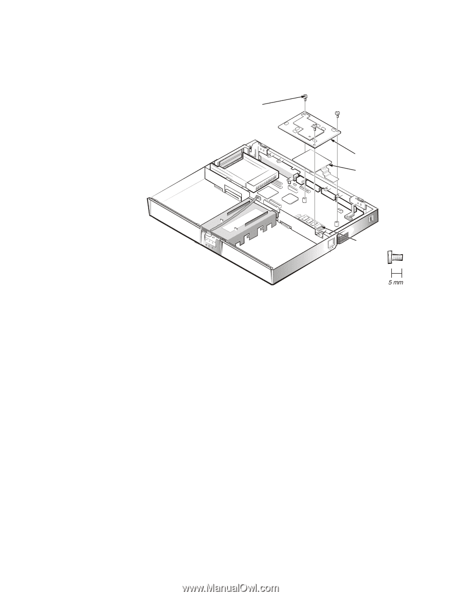
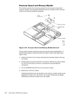
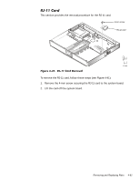
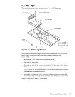
This section provides the removal procedure for the processor board and memory module. The processor board and memory module can be removed without removing the palmrest assembly. 5-mm screws (3) processor board SODIMM heat sink memory module This procedure assumes that you have removed the heat exchanger/fan. To remove the processor board and memory module, follow these steps (see Figure 4-39): 1. Remove the three 5-mm screws securing the processor board to the sys- tem board. 2. Gently pull the processor board off of connector JP15 on the system board. Do not rock the board to remove it, because this may damage the connectors. 3. Lift the SODIMM heat sink off of the memory module. 4. Remove the memory module. Carefully spread the inner metal tabs of the memory module socket to disengage the module from the socket. The module should pop up slightly. Then pull the memory module out of the socket. 4-58
-
 1
1 -
2
-
3
-
4
-
5
-
6
-
7
-
8
-
9
-
10
-
11
-
12
-
13
-
14
-
15
-
16
-
17
-
18
-
19
-
20
-
21
-
22
-
23
-
24
-
25
-
26
-
27
-
28
-
29
-
30
-
31
-
32
-
33
-
34
-
35
-
36
-
37
-
38
-
39
-
40
-
41
-
42
-
43
-
44
-
45
-
46
-
47
-
48
-
49
-
50
-
51
-
52
-
53
-
54
-
55
-
56
-
57
-
58
-
59
-
60
-
61
-
62
-
63
-
64
-
65
-
66
-
67
-
68
-
69
-
70
-
71
-
72
-
73
-
74
-
75
-
76
-
77
-
78
-
79
-
80
-
81
-
82
-
83
-
84
-
85
-
86
-
 87
87 -
 88
88 -
 89
89 -
 90
90 -
 91
91 -
 92
92 -
 93
93 -
 94
94 -
 95
95 -
 96
96 -
 97
97 -
98
-
99
-
100
-
101
-
102
-
103
-
104
 |
 |