Dell Inspiron 7000 Dell Inspiron 7000 Service Manual - Page 73
Loosen the 3-mm screw securing the inverter board.
 |
View all Dell Inspiron 7000 manuals
Add to My Manuals
Save this manual to your list of manuals |
Page 73 highlights
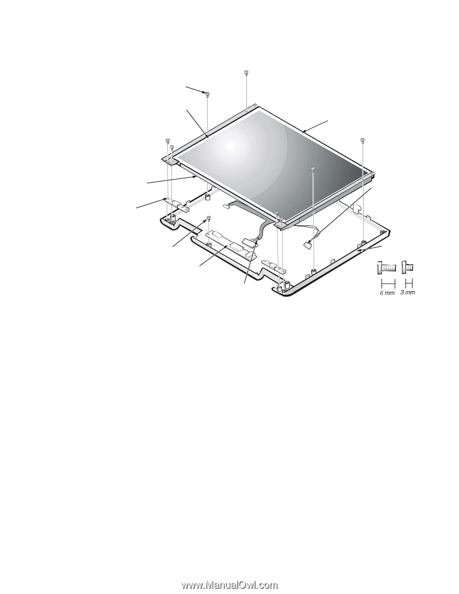
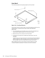
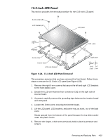
This section provides the removal procedure for the 13.3-inch LCD panel. 6-mm screws (8) LCD brackets (2) LCD panel carrier tray hinges(2) 3-mm screw inverter board LCD wire harness CCFL cable back cover This procedure assumes that you have removed the front bezel. Follow these steps to remove the 13.3-inch LCD panel (see Figure 4-26): 1. Remove the eight 6-mm screws that secure the left and right LCD brackets to the front plastic cover. 2. Detach the LCD wire harness from connector CN2 on the right side of inverter board. 3. If present, carefully remove the grounding tape between the inverter board and LCD panel. 4. Loosen the 3-mm screw securing the inverter board. 5. Lift the LCD panel, LCD brackets, and carrier tray, as a unit, out of the back cover. Rotate upward from the bottom of the panel because the top slides underneath the plastic hooks. 6. Remove the hinges, which were previously held in place by pressure and screws. Removing and Replacing Parts 4-39
-
 1
1 -
2
-
3
-
4
-
5
-
6
-
7
-
8
-
9
-
10
-
11
-
12
-
13
-
14
-
15
-
16
-
17
-
18
-
19
-
20
-
21
-
22
-
23
-
24
-
25
-
26
-
27
-
28
-
29
-
30
-
31
-
32
-
33
-
34
-
35
-
36
-
37
-
38
-
39
-
40
-
41
-
42
-
43
-
44
-
45
-
46
-
47
-
48
-
49
-
50
-
51
-
52
-
53
-
54
-
55
-
56
-
57
-
58
-
59
-
60
-
61
-
62
-
63
-
64
-
65
-
66
-
67
-
 68
68 -
 69
69 -
 70
70 -
 71
71 -
 72
72 -
 73
73 -
 74
74 -
 75
75 -
 76
76 -
 77
77 -
 78
78 -
79
-
80
-
81
-
82
-
83
-
84
-
85
-
86
-
87
-
88
-
89
-
90
-
91
-
92
-
93
-
94
-
95
-
96
-
97
-
98
-
99
-
100
-
101
-
102
-
103
-
104
 |
 |