Dell Inspiron 7000 Dell Inspiron 7000 Service Manual - Page 72
Carefully insert your fingers between the LCD panel and the bezel. Roll
 |
View all Dell Inspiron 7000 manuals
Add to My Manuals
Save this manual to your list of manuals |
Page 72 highlights
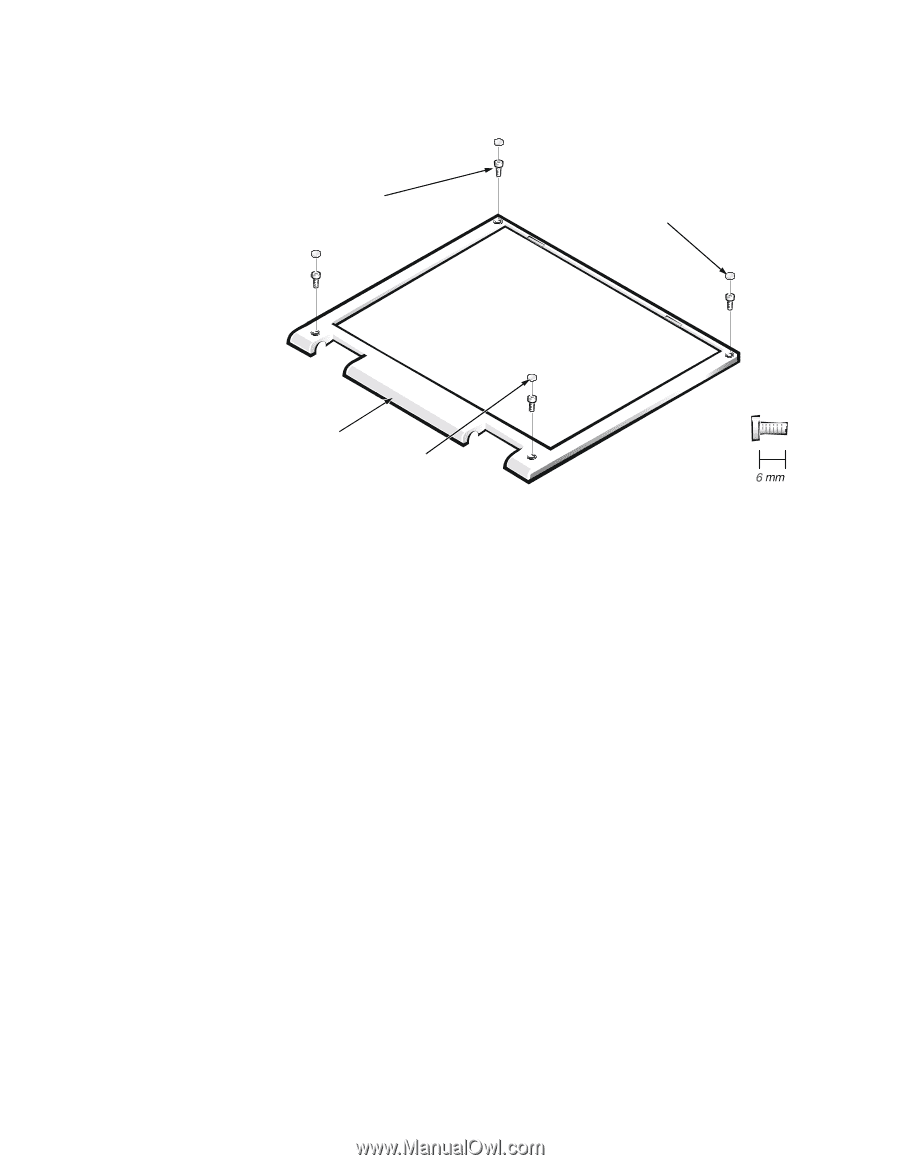
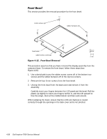
This section provides the removal procedure for the front bezel. 6-mm screws (4) rubber bumpers (2) front bezel rubber screw covers (2) This procedure assumes that you have removed the display assembly from the computer base. To remove the front bezel, follow these steps (see Figure 4-25): 1. Use a dental pick to pry the rubber screw covers off of the bottom two screws and the rubber bumpers off of the top two screws. 2. Remove the four 6-mm screws from the front bezel. 3. Unsnap the front bezel from the back cover and remove it from the assembly. Carefully insert your fingers between the LCD panel and the bezel. Roll the plastic up slightly to insert your fingers further in, and then lift upward to free the snaps. Start at the middle bottom and then work around. When replacing the bezel, ensure that the LCD wire harness is routed correctly through the openings in the back cover and is not pinched. 4-38
-
 1
1 -
2
-
3
-
4
-
5
-
6
-
7
-
8
-
9
-
10
-
11
-
12
-
13
-
14
-
15
-
16
-
17
-
18
-
19
-
20
-
21
-
22
-
23
-
24
-
25
-
26
-
27
-
28
-
29
-
30
-
31
-
32
-
33
-
34
-
35
-
36
-
37
-
38
-
39
-
40
-
41
-
42
-
43
-
44
-
45
-
46
-
47
-
48
-
49
-
50
-
51
-
52
-
53
-
54
-
55
-
56
-
57
-
58
-
59
-
60
-
61
-
62
-
63
-
64
-
65
-
66
-
 67
67 -
 68
68 -
 69
69 -
 70
70 -
 71
71 -
 72
72 -
 73
73 -
 74
74 -
 75
75 -
 76
76 -
 77
77 -
78
-
79
-
80
-
81
-
82
-
83
-
84
-
85
-
86
-
87
-
88
-
89
-
90
-
91
-
92
-
93
-
94
-
95
-
96
-
97
-
98
-
99
-
100
-
101
-
102
-
103
-
104
 |
 |