Dell Inspiron 7000 Dell Inspiron 7000 Service Manual - Page 71
nector to release it.
 |
View all Dell Inspiron 7000 manuals
Add to My Manuals
Save this manual to your list of manuals |
Page 71 highlights
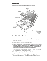
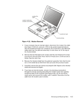
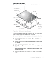
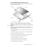
This section provides the removal procedure for the display assembly. 6-mm screws (4) hinges (2) hinge saddles (2) LCD wire harness connector JP3 This procedure assumes that you have removed the keyboard and thermal shield. To remove the display assembly from the computer, follow these steps (see Figure 4-24): 1. Disconnect the LCD wire harness from connector JP3. Use a dental pick or flat-blade screwdriver to pry up each end of the connector to release it. 2. Close the display. 3. Remove the four 6-mm screws that secure the two hinges. 4. Unlatch the display assembly and lift the assembly off the computer base. Removing and Replacing Parts 4-37
-
 1
1 -
2
-
3
-
4
-
5
-
6
-
7
-
8
-
9
-
10
-
11
-
12
-
13
-
14
-
15
-
16
-
17
-
18
-
19
-
20
-
21
-
22
-
23
-
24
-
25
-
26
-
27
-
28
-
29
-
30
-
31
-
32
-
33
-
34
-
35
-
36
-
37
-
38
-
39
-
40
-
41
-
42
-
43
-
44
-
45
-
46
-
47
-
48
-
49
-
50
-
51
-
52
-
53
-
54
-
55
-
56
-
57
-
58
-
59
-
60
-
61
-
62
-
63
-
64
-
65
-
 66
66 -
 67
67 -
 68
68 -
 69
69 -
 70
70 -
 71
71 -
 72
72 -
 73
73 -
 74
74 -
 75
75 -
 76
76 -
77
-
78
-
79
-
80
-
81
-
82
-
83
-
84
-
85
-
86
-
87
-
88
-
89
-
90
-
91
-
92
-
93
-
94
-
95
-
96
-
97
-
98
-
99
-
100
-
101
-
102
-
103
-
104
 |
 |

Removing and Replacing Parts
4-37
’LVSOD\±$VVHPEO\
This section provides the removal procedure for the display assembly.
)LJXUH±·´µ·³±±’LVSOD\±$VVHPEO\±5HPRYDO
This procedure assumes that you have removed the keyboard and thermal
shield. To remove the display assembly from the computer, follow these steps
(see Figure 4-24):
1.
Disconnect the LCD wire harness from connector JP3.
Use a dental pick or flat-blade screwdriver to pry up each end of the con-
nector to release it.
2.
Close the display.
3.
Remove the four 6-mm screws that secure the two hinges.
4.
Unlatch the display assembly and lift the assembly off the computer base.
6-mm screws (4)
hinge saddles (2)
connector
JP3
hinges (2)
LCD wire
harness