Dell Inspiron 7000 Dell Inspiron 7000 Service Manual - Page 94
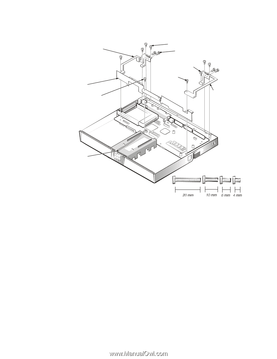
This provides the removal procedure for the hinge saddles.
 |
View all Dell Inspiron 7000 manuals
Add to My Manuals
Save this manual to your list of manuals |
Page 94 highlights
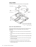
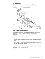
This section provides the removal procedure for the hinge saddles. left hinge saddle 4-mm screws (4) 4-mm screws (4) plastic frame 6-mm screw (1) 10-mm screws (2) 20-mm screws (2) right hinge saddle LED cable This procedure assumes that you have removed the PC Card heat sink and LVDS board. To remove the hinge saddles, follow these steps (see Figure 4-40): 1. Remove the four 4-mm screws from the top of the left and right hinge saddles. 2. Remove the four 4-mm screws from the back of the computer above the ports. 3. Remove the 10-mm screw and 20-mm screw from the right hinge saddle and remove the saddle. 4. Remove the 10-mm screw and 20-mm screw from the left hinge saddle and remove the saddle. 5. Disconnect the LED cable from connector J6 on the system board. 6. Remove the 6-mm screw from the plastic frame, remove any tape, and remove the plastic frame. 4-60
-
 1
1 -
2
-
3
-
4
-
5
-
6
-
7
-
8
-
9
-
10
-
11
-
12
-
13
-
14
-
15
-
16
-
17
-
18
-
19
-
20
-
21
-
22
-
23
-
24
-
25
-
26
-
27
-
28
-
29
-
30
-
31
-
32
-
33
-
34
-
35
-
36
-
37
-
38
-
39
-
40
-
41
-
42
-
43
-
44
-
45
-
46
-
47
-
48
-
49
-
50
-
51
-
52
-
53
-
54
-
55
-
56
-
57
-
58
-
59
-
60
-
61
-
62
-
63
-
64
-
65
-
66
-
67
-
68
-
69
-
70
-
71
-
72
-
73
-
74
-
75
-
76
-
77
-
78
-
79
-
80
-
81
-
82
-
83
-
84
-
85
-
86
-
87
-
88
-
 89
89 -
 90
90 -
 91
91 -
 92
92 -
 93
93 -
 94
94 -
 95
95 -
 96
96 -
 97
97 -
 98
98 -
 99
99 -
100
-
101
-
102
-
103
-
104
 |
 |