Dell Inspiron 7000 Dell Inspiron 7000 Service Manual - Page 35
Number 1 Phillips-head screwdriver
 |
View all Dell Inspiron 7000 manuals
Add to My Manuals
Save this manual to your list of manuals |
Page 35 highlights
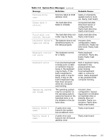
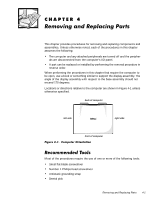
This chapter provides procedures for removing and replacing components and assemblies. Unless otherwise noted, each of the procedures in this chapter assumes the following: The computer and any attached peripherals are turned off and the peripherals are disconnected from the computer's I/O panel. A part can be replaced or installed by performing the removal procedure in reverse order. When performing the procedures in this chapter that require the computer to be open, use a book or something similar to support the display assembly. The angle of the display assembly with respect to the base assembly should not exceed 170 degrees. Locations or directions relative to the computer are shown in Figure 4-1 unless otherwise specified. back of computer left side right side front of computer Most of the procedures require the use of one or more of the following tools: Small flat-blade screwdriver Number 1 Phillips-head screwdriver Antistatic grounding strap Dental pick Removing and Replacing Parts 4-1
-
 1
1 -
2
-
3
-
4
-
5
-
6
-
7
-
8
-
9
-
10
-
11
-
12
-
13
-
14
-
15
-
16
-
17
-
18
-
19
-
20
-
21
-
22
-
23
-
24
-
25
-
26
-
27
-
28
-
29
-
 30
30 -
 31
31 -
 32
32 -
 33
33 -
 34
34 -
 35
35 -
 36
36 -
 37
37 -
 38
38 -
 39
39 -
 40
40 -
41
-
42
-
43
-
44
-
45
-
46
-
47
-
48
-
49
-
50
-
51
-
52
-
53
-
54
-
55
-
56
-
57
-
58
-
59
-
60
-
61
-
62
-
63
-
64
-
65
-
66
-
67
-
68
-
69
-
70
-
71
-
72
-
73
-
74
-
75
-
76
-
77
-
78
-
79
-
80
-
81
-
82
-
83
-
84
-
85
-
86
-
87
-
88
-
89
-
90
-
91
-
92
-
93
-
94
-
95
-
96
-
97
-
98
-
99
-
100
-
101
-
102
-
103
-
104
 |
 |