Dell Inspiron 7000 Dell Inspiron 7000 Service Manual - Page 66
H\erdug - keyboard will not work
 |
View all Dell Inspiron 7000 manuals
Add to My Manuals
Save this manual to your list of manuals |
Page 66 highlights
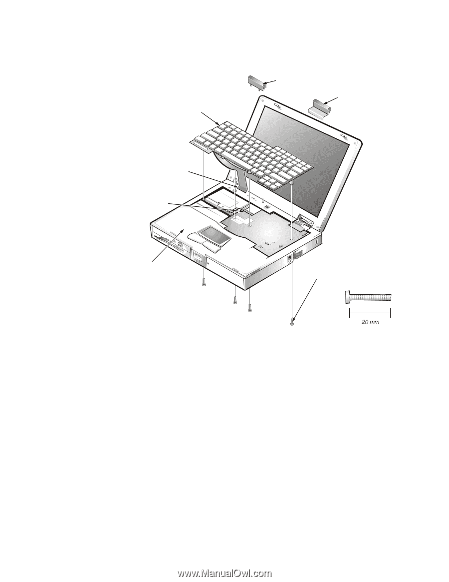
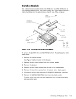
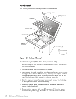
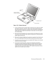
This section provides the removal procedure for the keyboard. keyboard left hinge cover right hinge cover keyboard cable ZIF connector palmrest assembly 20-mm screws (4) To remove the keyboard, follow these steps (see Figure 4-21): 1. Turn the computer over and remove the four 20-mm screws from the bottom of the computer. 2. Turn the computer back over and open the display. 3. Insert a small flat-blade screwdriver or scribe along the right top of the keyboard, just above the row of function keys. Working from right to left, free the keyboard by prying it toward the front of the unit. When free, lift the top of the keyboard slightly to clear the palmrest assembly. 4. Slide the keyboard toward the display assembly to release the front edge of the keyboard from the palmrest assembly. 5. Rotate the bottom of the keyboard up toward the display assembly to expose the keyboard cable. 6. Disconnect the keyboard cable from ZIF connector JP14 on the system board. Use the pick to pry up the latches on each side of the connector. 4-32
-
 1
1 -
2
-
3
-
4
-
5
-
6
-
7
-
8
-
9
-
10
-
11
-
12
-
13
-
14
-
15
-
16
-
17
-
18
-
19
-
20
-
21
-
22
-
23
-
24
-
25
-
26
-
27
-
28
-
29
-
30
-
31
-
32
-
33
-
34
-
35
-
36
-
37
-
38
-
39
-
40
-
41
-
42
-
43
-
44
-
45
-
46
-
47
-
48
-
49
-
50
-
51
-
52
-
53
-
54
-
55
-
56
-
57
-
58
-
59
-
60
-
 61
61 -
 62
62 -
 63
63 -
 64
64 -
 65
65 -
 66
66 -
 67
67 -
 68
68 -
 69
69 -
 70
70 -
 71
71 -
72
-
73
-
74
-
75
-
76
-
77
-
78
-
79
-
80
-
81
-
82
-
83
-
84
-
85
-
86
-
87
-
88
-
89
-
90
-
91
-
92
-
93
-
94
-
95
-
96
-
97
-
98
-
99
-
100
-
101
-
102
-
103
-
104
 |
 |