Dell Inspiron 7000 Dell Inspiron 7000 Service Manual - Page 87
System board
 |
View all Dell Inspiron 7000 manuals
Add to My Manuals
Save this manual to your list of manuals |
Page 87 highlights
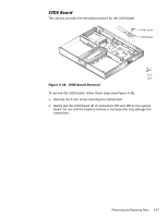
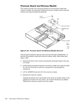
The following subsections provide removal and replacement procedures for most components of the base assembly. The procedures in these subsections assume that the keyboard, thermal shield, display assembly, and palmrest assembly have been removed. The base assembly consists of the following components: PC Card heat sink Heat exchanger/fan DC-DC board LVDS board RJ-11 card Processor board and memory module Hinge saddles System board PC Card cage Audio board and audio thermal shield Latch assembly Kensington lock Bottom case Removing and Replacing Parts 4-53
-
 1
1 -
2
-
3
-
4
-
5
-
6
-
7
-
8
-
9
-
10
-
11
-
12
-
13
-
14
-
15
-
16
-
17
-
18
-
19
-
20
-
21
-
22
-
23
-
24
-
25
-
26
-
27
-
28
-
29
-
30
-
31
-
32
-
33
-
34
-
35
-
36
-
37
-
38
-
39
-
40
-
41
-
42
-
43
-
44
-
45
-
46
-
47
-
48
-
49
-
50
-
51
-
52
-
53
-
54
-
55
-
56
-
57
-
58
-
59
-
60
-
61
-
62
-
63
-
64
-
65
-
66
-
67
-
68
-
69
-
70
-
71
-
72
-
73
-
74
-
75
-
76
-
77
-
78
-
79
-
80
-
81
-
 82
82 -
 83
83 -
 84
84 -
 85
85 -
 86
86 -
 87
87 -
 88
88 -
 89
89 -
 90
90 -
 91
91 -
 92
92 -
93
-
94
-
95
-
96
-
97
-
98
-
99
-
100
-
101
-
102
-
103
-
104
 |
 |

Removing and Replacing Parts
4-53
%DVH±$VVHPEO\±DQG±&RPSRQHQWV
The following subsections provide removal and replacement procedures for
most components of the base assembly. The procedures in these subsections
assume that the keyboard, thermal shield, display assembly, and palmrest
assembly have been removed.
The base assembly consists of the following components:
¹
PC Card heat sink
¹
Heat exchanger/fan
¹
DC-DC board
¹
LVDS board
¹
RJ-11 card
¹
Processor board and memory module
¹
Hinge saddles
¹
System board
¹
PC Card cage
¹
Audio board and audio thermal shield
¹
Latch assembly
¹
Kensington lock
¹
Bottom case