Dell Inspiron 7000 Dell Inspiron 7000 Service Manual - Page 81
the hidden tabs spaced around the sides and along the top of the battery
 |
View all Dell Inspiron 7000 manuals
Add to My Manuals
Save this manual to your list of manuals |
Page 81 highlights
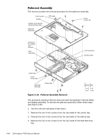
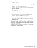
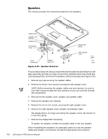
5. Turn the unit back over. 6. Remove the three 6-mm screws from the top of the base assembly, along the back edge. 7. Remove the 6-mm screw from the DC-DC board. 8. Remove the 4-mm screw and the washer securing the grounding strap to the PC Card heat shield. 9. Disconnect the speaker wire harness from connector JP18 on the left side of the system board. This wire harness also contains wiring for the touch pad and the touch pad buttons. 10. Disconnect the LED cable from connector JP10 on the system board. 11. Remove the palmrest assembly from the base assembly. Start at the back right of the computer and move forward around the computer. Carefully lift the palmrest assembly up and pull it forward to unsnap the hidden tabs spaced around the sides and along the top of the battery bay and options bay. When replacing the palmrest assembly, orient the assembly in its original position on the base assembly and press firmly near each tab until the palmrest assembly snaps into place. Start at the front to align those tabs first. Make sure that all the tabs are aligned. The following subsections provide removal and replacement procedures for the components of the palmrest assembly. Removing and Replacing Parts 4-47
-
 1
1 -
2
-
3
-
4
-
5
-
6
-
7
-
8
-
9
-
10
-
11
-
12
-
13
-
14
-
15
-
16
-
17
-
18
-
19
-
20
-
21
-
22
-
23
-
24
-
25
-
26
-
27
-
28
-
29
-
30
-
31
-
32
-
33
-
34
-
35
-
36
-
37
-
38
-
39
-
40
-
41
-
42
-
43
-
44
-
45
-
46
-
47
-
48
-
49
-
50
-
51
-
52
-
53
-
54
-
55
-
56
-
57
-
58
-
59
-
60
-
61
-
62
-
63
-
64
-
65
-
66
-
67
-
68
-
69
-
70
-
71
-
72
-
73
-
74
-
75
-
 76
76 -
 77
77 -
 78
78 -
 79
79 -
 80
80 -
 81
81 -
 82
82 -
 83
83 -
 84
84 -
 85
85 -
 86
86 -
87
-
88
-
89
-
90
-
91
-
92
-
93
-
94
-
95
-
96
-
97
-
98
-
99
-
100
-
101
-
102
-
103
-
104
 |
 |