Dell Inspiron 7000 Dell Inspiron 7000 Service Manual - Page 99
Remove the latch cover.
 |
View all Dell Inspiron 7000 manuals
Add to My Manuals
Save this manual to your list of manuals |
Page 99 highlights
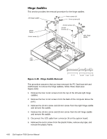
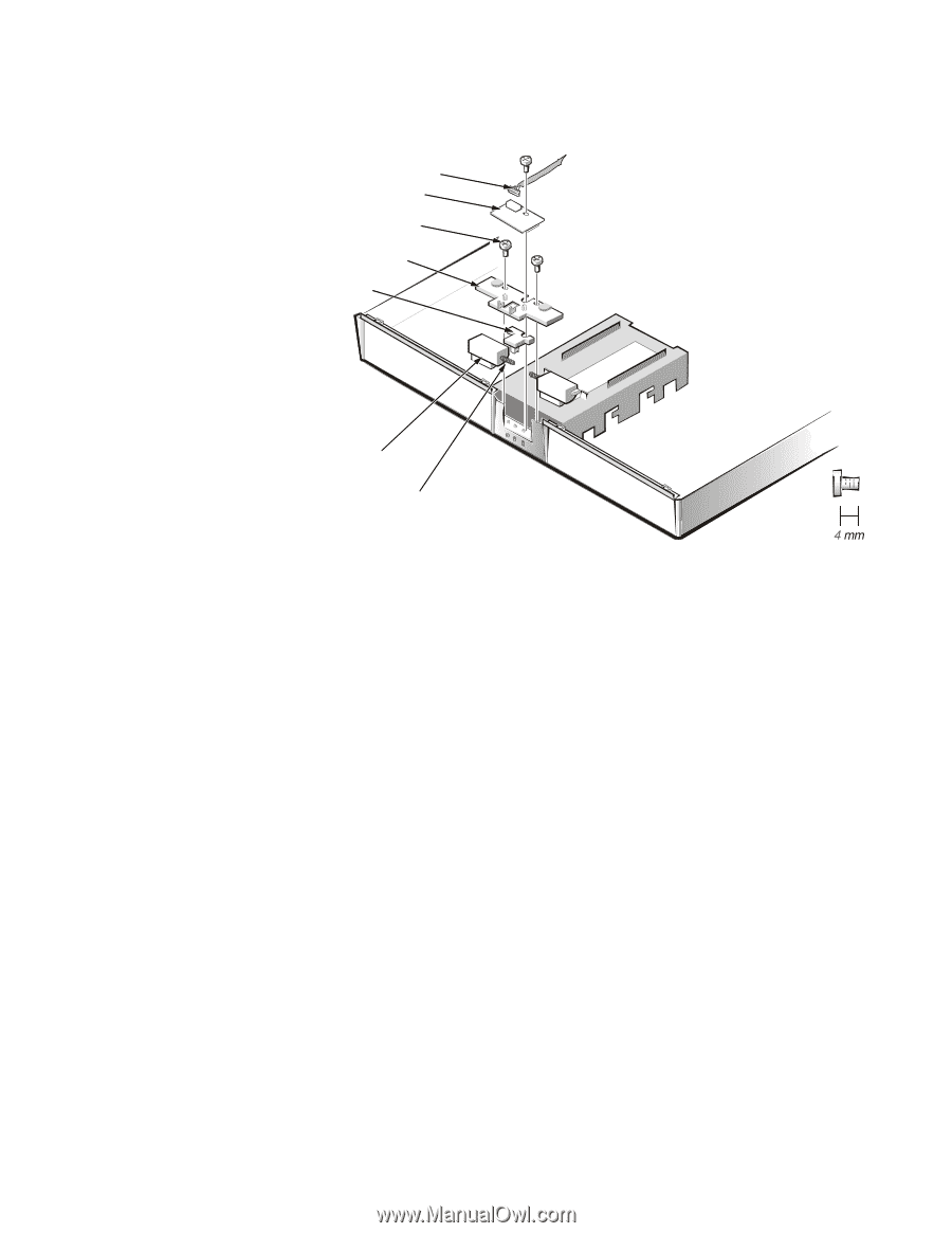
This section provides the removal procedure for the latch assembly. LED cable LED board 4-mm screws (3) latch cover center lock latches (2) springs (2) To remove the latch assembly, follow these steps (see Figure 4-45): 1. Disconnect the LED cable from connector JP2 on the LED board. 2. Remove the 4-mm screw securing the LED board to the plastic base. 3. Remove the LED board. 4. Remove the two 4-mm screws holding the latch cover for the battery bay and options bay. 5. Remove the latch cover. 6. Remove the center lock over the two latches with springs. 7. Remove each spring and latch. Be careful not to lose the small springs. Removing and Replacing Parts 4-65
-
 1
1 -
2
-
3
-
4
-
5
-
6
-
7
-
8
-
9
-
10
-
11
-
12
-
13
-
14
-
15
-
16
-
17
-
18
-
19
-
20
-
21
-
22
-
23
-
24
-
25
-
26
-
27
-
28
-
29
-
30
-
31
-
32
-
33
-
34
-
35
-
36
-
37
-
38
-
39
-
40
-
41
-
42
-
43
-
44
-
45
-
46
-
47
-
48
-
49
-
50
-
51
-
52
-
53
-
54
-
55
-
56
-
57
-
58
-
59
-
60
-
61
-
62
-
63
-
64
-
65
-
66
-
67
-
68
-
69
-
70
-
71
-
72
-
73
-
74
-
75
-
76
-
77
-
78
-
79
-
80
-
81
-
82
-
83
-
84
-
85
-
86
-
87
-
88
-
89
-
90
-
91
-
92
-
93
-
 94
94 -
 95
95 -
 96
96 -
 97
97 -
 98
98 -
 99
99 -
 100
100 -
 101
101 -
 102
102 -
 103
103 -
 104
104
 |
 |
Removing and Replacing Parts
4-65
/DWFK±$VVHPEO\
This section provides the removal procedure for the latch assembly.
)LJXUH±·´·º³±±/DWFK±$VVHPEO\±5HPRYDO±
To remove the latch assembly, follow these steps (see Figure 4-45):
1.
Disconnect the LED cable from connector JP2 on the LED board.
2.
Remove the 4-mm screw securing the LED board to the plastic base.
3.
Remove the LED board.
4.
Remove the two 4-mm screws holding the latch cover for the battery bay
and options bay.
5.
Remove the latch cover.
6.
Remove the center lock over the two latches with springs.
7.
Remove each spring and latch.
Be careful not to lose the small springs.
LED board
LED cable
latch cover
center lock
latches (2)
springs (2)
4-mm screws (3)