Dell Inspiron 7000 Dell Inspiron 7000 Service Manual - Page 65
Be careful not to scratch the computer plastic case by allowing the screws - keyboard not working
 |
View all Dell Inspiron 7000 manuals
Add to My Manuals
Save this manual to your list of manuals |
Page 65 highlights
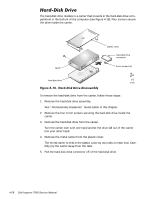
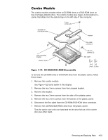
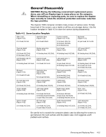
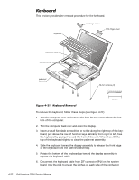
The Inspiron 7000 computer contains many screws of various sizes. To help keep track of the screws, use a tackle or pill box as a storage device. Use the location template in Table 4-2 to store the screws during disassembly. Video card (Figure 4-10): 2X K-head, M2x3L Thermal shield (Figure 4-22): Hard-disk drive (Figure 4-18): 4X K-head M3x3L Display assembly (Figure 4-24): Combo module (Figure 4-19, 4-20): 2X K-head, M2x2.5L 3X K-head, M2.5x3L 8X K-head M2x3L Front bezel (Figure 4-25): Keyboard (Figure 4-21): 4X pan head, M2.5x20L LCD panel (13.3") (Figure 4-26): 1X K-head, M2.5x4L 4X flat head, M2x4L LCD brackets (13.3") (Figure 4-27): 4X binding head, M2.5x6L 4X binding head, M2.5x6L 8X binding head, M2.5x6L Inverter board (Figure 4-26, 4-28): LCD panel (14.1") (Figure 4-28): Palmrest assembly (Figure 4-30): 4X binding head, M2.5x6L 1X K-head, M2.5x3L IR board (Figure 4-31): 2X K-head M2.5x4L PC Card heat sink (Figure 4-35): Hard-disk drive heat shield (Figure 4-32): 5X K-head M2.5x4L Heat exchanger/fan (Figure 4-36): 4X pan head, M2x4L 8X binding head, M2.5x6L Touch pad assembly (Figure 4-33): 4X K-head M2.5x4L 3X K-head M2.5x4L LVDS board (Figure 4-38): 4X binding head, M2.5x6L 6X K-head, M2.5x4L 1X K-head, M2.5x4L Speakers (Figure 4-34): 5X K-head M2.5x4L Processor board (Figure 4-39): 2X K-head, M2.5x4L Hinge saddles (Figure 4-40): 2X binding head, M2x5L Left hinge saddle (Figure 4-40): 1X K-head, M2.5x4L Right hinge saddle (Figure 4-40): 1X binding head, M2.5x6L 4X K-head, M2.5x4L 4X K-head, M2.5x4L 1X binding head M2.5x10L 1X pan head, M2.5x20L 1X pan head, M2.5x20L 1X binding head M2.5x10L System board (Figure 4-42): PC Card cage (Figure 4-43): Audio thermal shield (Figure 4-44): 3X binding head, M2x5L RJ-11 card (Figure 4-41): 1X K-head, M2.5x4L Latch assembly (Figure 4-45): 3X K-head, M2.5x4L 1X K-head, M2.5x4L 4X pan head, M2x18L 1X binding head, M2.5x10L 1X K-head, M2.5x4L 2X K-head, M2.5x4L Be careful not to scratch the computer plastic case by allowing the screws to get between the work surface and the plastic case. Dell suggests a soft padded work surface. Removing and Replacing Parts 4-31
-
 1
1 -
2
-
3
-
4
-
5
-
6
-
7
-
8
-
9
-
10
-
11
-
12
-
13
-
14
-
15
-
16
-
17
-
18
-
19
-
20
-
21
-
22
-
23
-
24
-
25
-
26
-
27
-
28
-
29
-
30
-
31
-
32
-
33
-
34
-
35
-
36
-
37
-
38
-
39
-
40
-
41
-
42
-
43
-
44
-
45
-
46
-
47
-
48
-
49
-
50
-
51
-
52
-
53
-
54
-
55
-
56
-
57
-
58
-
59
-
 60
60 -
 61
61 -
 62
62 -
 63
63 -
 64
64 -
 65
65 -
 66
66 -
 67
67 -
 68
68 -
 69
69 -
 70
70 -
71
-
72
-
73
-
74
-
75
-
76
-
77
-
78
-
79
-
80
-
81
-
82
-
83
-
84
-
85
-
86
-
87
-
88
-
89
-
90
-
91
-
92
-
93
-
94
-
95
-
96
-
97
-
98
-
99
-
100
-
101
-
102
-
103
-
104
 |
 |