Dell Inspiron 7000 Dell Inspiron 7000 Service Manual - Page 82
Remove the two 4-mm screws securing the IR board.
 |
View all Dell Inspiron 7000 manuals
Add to My Manuals
Save this manual to your list of manuals |
Page 82 highlights
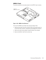
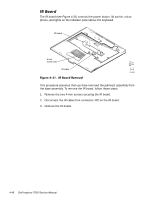
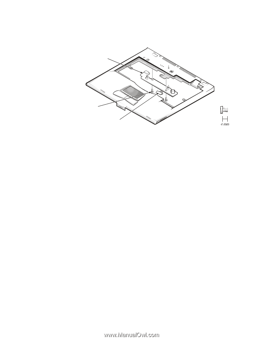
The IR board (see Figure 4-31) controls the power button, lid switch, microphone, and lights on the indicator panel above the keyboard. IR board 4-mm screws (2) IR cable This procedure assumes that you have removed the palmrest assembly from the base assembly. To remove the IR board, follow these steps: 1. Remove the two 4-mm screws securing the IR board. 2. Disconnect the IR cable from connector JP2 on the IR board. 3. Remove the IR board. 4-48
-
 1
1 -
2
-
3
-
4
-
5
-
6
-
7
-
8
-
9
-
10
-
11
-
12
-
13
-
14
-
15
-
16
-
17
-
18
-
19
-
20
-
21
-
22
-
23
-
24
-
25
-
26
-
27
-
28
-
29
-
30
-
31
-
32
-
33
-
34
-
35
-
36
-
37
-
38
-
39
-
40
-
41
-
42
-
43
-
44
-
45
-
46
-
47
-
48
-
49
-
50
-
51
-
52
-
53
-
54
-
55
-
56
-
57
-
58
-
59
-
60
-
61
-
62
-
63
-
64
-
65
-
66
-
67
-
68
-
69
-
70
-
71
-
72
-
73
-
74
-
75
-
76
-
 77
77 -
 78
78 -
 79
79 -
 80
80 -
 81
81 -
 82
82 -
 83
83 -
 84
84 -
 85
85 -
 86
86 -
 87
87 -
88
-
89
-
90
-
91
-
92
-
93
-
94
-
95
-
96
-
97
-
98
-
99
-
100
-
101
-
102
-
103
-
104
 |
 |
4-48
’HOO±,QVSLURQ±²³³³±6HUYLFH±0DQXDO
,5±%RDUG
The IR board (see Figure 4-31) controls the power button, lid switch, micro-
phone, and lights on the indicator panel above the keyboard.
)LJXUH±·´¶²³±±,5±%RDUG±5HPRYDO±
This procedure assumes that you have removed the palmrest assembly from
the base assembly. To remove the IR board, follow these steps:
1.
Remove the two 4-mm screws securing the IR board.
2.
Disconnect the IR cable from connector JP2 on the IR board.
3.
Remove the IR board.
4-mm
screws (2)
IR board
IR cable