Dell Inspiron 7000 Dell Inspiron 7000 Service Manual - Page 5

Audio Card and Audio Thermal Shield Removal .. 4-64 - no lcd display

Page 5 highlights

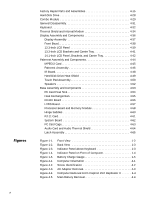
Figure 4-6. Figure 4-7. Figure 4-8. Figure 4-9. Figure 4-10. Figure 4-11. Figure 4-12. Figure 4-13. Figure 4-14. Figure 4-15. Figure 4-16. Figure 4-17. Figure 4-18. Figure 4-19. Figure 4-20. Figure 4-21. Figure 4-22. Figure 4-23. Figure 4-24. Figure 4-25. Figure 4-26. Figure 4-27. Figure 4-28. Figure 4-29. Figure 4-30. Figure 4-31. Figure 4-32. Figure 4-33. Figure 4-34. Figure 4-35. Figure 4-36. Figure 4-37. Figure 4-38. Figure 4-39. Figure 4-40. Figure 4-41. Figure 4-42. Figure 4-43. Figure 4-44. Figure 4-45. PC Card Removal 4-5 Hard-Disk Drive Removal 4-6 Memory Module and Video Card Cover Removal 4-6 Memory Module Removal 4-7 Video Card Removal 4-7 Combo Module or Secondary Battery Removal 4-8 Releasing a ZIF Connector 4-9 Exploded View-Computer 4-10 Exploded View-13.3-Inch Display Assembly 4-11 Exploded View-14.1-Inch Display Assembly 4-12 Exploded View-Palmrest Assembly 4-13 Exploded View-Base Assembly 4-14 Hard-Disk Drive Disassembly 4-28 CD-ROM/DVD-ROM Disassembly 4-29 Diskette Drive Disassembly 4-30 Keyboard Removal 4-32 Thermal Shield Removal 4-34 Modem Removal 4-35 Display Assembly Removal 4-37 Front Bezel Removal 4-38 13.3-Inch LCD Panel Removal 4-39 13.3-Inch LCD Brackets and Carrier Tray Removal 4-41 14.1-Inch LCD Panel Removal 4-42 MPEG-2 Card Removal 4-45 Palmrest Assembly Removal 4-46 IR Board Removal 4-48 Hard-Disk Drive Heat Shield Removal 4-49 Touch Pad Assembly Removal 4-50 Speaker Removal 4-52 PC Card Heat Sink Removal 4-54 Heat Exchanger/Fan Removal 4-55 DC-DC Board Removal 4-56 LVDS Board Removal 4-57 Processor Board and Memory Module Removal 4-58 Hinge Saddle Removal 4-60 RJ-11 Card Removal 4-61 System Board Removal 4-62 PC Card Cage Removal 4-63 Audio Card and Audio Thermal Shield Removal 4-64 Latch Assembly Removal 4-65 vii

  • 1
  • 2
  • 3
  • 4
  • 5
  • 6
  • 7
  • 8
  • 9
  • 10
  • 11
  • 12
  • 13
  • 14
  • 15
  • 16
  • 17
  • 18
  • 19
  • 20
  • 21
  • 22
  • 23
  • 24
  • 25
  • 26
  • 27
  • 28
  • 29
  • 30
  • 31
  • 32
  • 33
  • 34
  • 35
  • 36
  • 37
  • 38
  • 39
  • 40
  • 41
  • 42
  • 43
  • 44
  • 45
  • 46
  • 47
  • 48
  • 49
  • 50
  • 51
  • 52
  • 53
  • 54
  • 55
  • 56
  • 57
  • 58
  • 59
  • 60
  • 61
  • 62
  • 63
  • 64
  • 65
  • 66
  • 67
  • 68
  • 69
  • 70
  • 71
  • 72
  • 73
  • 74
  • 75
  • 76
  • 77
  • 78
  • 79
  • 80
  • 81
  • 82
  • 83
  • 84
  • 85
  • 86
  • 87
  • 88
  • 89
  • 90
  • 91
  • 92
  • 93
  • 94
  • 95
  • 96
  • 97
  • 98
  • 99
  • 100
  • 101
  • 102
  • 103
  • 104

vii
Figure 4-6.
PC Card Removal . . . . . . . . . . . . . . . . . . . . . . . . . . . . . . . . . 4-5
Figure 4-7.
Hard-Disk Drive Removal . . . . . . . . . . . . . . . . . . . . . . . . . . . 4-6
Figure 4-8.
Memory Module and Video Card Cover Removal. . . . . . . . . 4-6
Figure 4-9.
Memory Module Removal. . . . . . . . . . . . . . . . . . . . . . . . . . . 4-7
Figure 4-10.
Video Card Removal . . . . . . . . . . . . . . . . . . . . . . . . . . . . . . . 4-7
Figure 4-11.
Combo Module or Secondary Battery Removal . . . . . . . . . . 4-8
Figure 4-12.
Releasing a ZIF Connector . . . . . . . . . . . . . . . . . . . . . . . . . . 4-9
Figure 4-13.
Exploded View—Computer. . . . . . . . . . . . . . . . . . . . . . . . . 4-10
Figure 4-14.
Exploded View—13.3-Inch Display Assembly. . . . . . . . . . . 4-11
Figure 4-15.
Exploded View—14.1-Inch Display Assembly. . . . . . . . . . . 4-12
Figure 4-16.
Exploded View—Palmrest Assembly . . . . . . . . . . . . . . . . . 4-13
Figure 4-17.
Exploded View—Base Assembly . . . . . . . . . . . . . . . . . . . . 4-14
Figure 4-18.
Hard-Disk Drive Disassembly . . . . . . . . . . . . . . . . . . . . . . . 4-28
Figure 4-19.
CD-ROM/DVD-ROM Disassembly . . . . . . . . . . . . . . . . . . . 4-29
Figure 4-20.
Diskette Drive Disassembly . . . . . . . . . . . . . . . . . . . . . . . . 4-30
Figure 4-21.
Keyboard Removal . . . . . . . . . . . . . . . . . . . . . . . . . . . . . . . 4-32
Figure 4-22.
Thermal Shield Removal . . . . . . . . . . . . . . . . . . . . . . . . . . . 4-34
Figure 4-23.
Modem Removal. . . . . . . . . . . . . . . . . . . . . . . . . . . . . . . . . 4-35
Figure 4-24.
Display Assembly Removal. . . . . . . . . . . . . . . . . . . . . . . . . 4-37
Figure 4-25.
Front Bezel Removal
. . . . . . . . . . . . . . . . . . . . . . . . . . . . . 4-38
Figure 4-26.
13.3-Inch LCD Panel Removal. . . . . . . . . . . . . . . . . . . . . . . 4-39
Figure 4-27.
13.3-Inch LCD Brackets and Carrier Tray Removal . . . . . . . 4-41
Figure 4-28.
14.1-Inch LCD Panel Removal. . . . . . . . . . . . . . . . . . . . . . . 4-42
Figure 4-29.
MPEG-2 Card Removal . . . . . . . . . . . . . . . . . . . . . . . . . . . . 4-45
Figure 4-30.
Palmrest Assembly Removal . . . . . . . . . . . . . . . . . . . . . . . 4-46
Figure 4-31.
IR Board Removal . . . . . . . . . . . . . . . . . . . . . . . . . . . . . . . . 4-48
Figure 4-32.
Hard-Disk Drive Heat Shield Removal. . . . . . . . . . . . . . . . . 4-49
Figure 4-33.
Touch Pad Assembly Removal . . . . . . . . . . . . . . . . . . . . . . 4-50
Figure 4-34.
Speaker Removal . . . . . . . . . . . . . . . . . . . . . . . . . . . . . . . . 4-52
Figure 4-35.
PC Card Heat Sink Removal . . . . . . . . . . . . . . . . . . . . . . . . 4-54
Figure 4-36.
Heat Exchanger/Fan Removal . . . . . . . . . . . . . . . . . . . . . . . 4-55
Figure 4-37.
DC-DC Board Removal . . . . . . . . . . . . . . . . . . . . . . . . . . . . 4-56
Figure 4-38.
LVDS Board Removal . . . . . . . . . . . . . . . . . . . . . . . . . . . . . 4-57
Figure 4-39.
Processor Board and Memory Module Removal . . . . . . . . 4-58
Figure 4-40.
Hinge Saddle Removal . . . . . . . . . . . . . . . . . . . . . . . . . . . . 4-60
Figure 4-41.
RJ-11 Card Removal . . . . . . . . . . . . . . . . . . . . . . . . . . . . . . 4-61
Figure 4-42.
System Board Removal. . . . . . . . . . . . . . . . . . . . . . . . . . . . 4-62
Figure 4-43.
PC Card Cage Removal . . . . . . . . . . . . . . . . . . . . . . . . . . . . 4-63
Figure 4-44.
Audio Card and Audio Thermal Shield Removal . . . . . . . . . 4-64
Figure 4-45.
Latch Assembly Removal . . . . . . . . . . . . . . . . . . . . . . . . . . 4-65