Dell Inspiron 7000 Dell Inspiron 7000 Service Manual - Page 84
button board.
 |
View all Dell Inspiron 7000 manuals
Add to My Manuals
Save this manual to your list of manuals |
Page 84 highlights
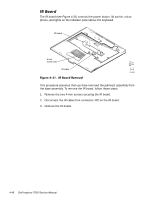
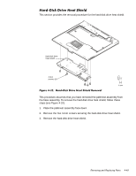
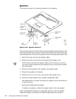
This section provides the removal procedure for the touch pad assembly. touch pad button board 4-mm screws (3) touch pad touch pad bracket 4-mm screws (4) touch pad flex cable ZIF connector This procedure assumes that you have removed the palmrest assembly from the base assembly and that you have removed the hard-disk drive heat shield. To remove the touch pad assembly, follow these steps (see Figure 4-33): 1. Remove the three 4-mm screws securing the touch pad button board. 2. Disconnect the two speaker cables from connectors JP5 and JP3 on the touch pad button board. 3. Disconnect the speaker wire harness from connector JP1 on the touch pad button board. 4. Disconnect the touch pad flex cable from ZIF connector JP4 on the touch pad button board. Use the pick to pry up the latches on each side of the connector. 5. Disconnect the touch pad flex cable from ZIF connector J1 on the touch pad. Use the pick to pry up the brown center piece on the connector. 4-50
-
 1
1 -
2
-
3
-
4
-
5
-
6
-
7
-
8
-
9
-
10
-
11
-
12
-
13
-
14
-
15
-
16
-
17
-
18
-
19
-
20
-
21
-
22
-
23
-
24
-
25
-
26
-
27
-
28
-
29
-
30
-
31
-
32
-
33
-
34
-
35
-
36
-
37
-
38
-
39
-
40
-
41
-
42
-
43
-
44
-
45
-
46
-
47
-
48
-
49
-
50
-
51
-
52
-
53
-
54
-
55
-
56
-
57
-
58
-
59
-
60
-
61
-
62
-
63
-
64
-
65
-
66
-
67
-
68
-
69
-
70
-
71
-
72
-
73
-
74
-
75
-
76
-
77
-
78
-
 79
79 -
 80
80 -
 81
81 -
 82
82 -
 83
83 -
 84
84 -
 85
85 -
 86
86 -
 87
87 -
 88
88 -
 89
89 -
90
-
91
-
92
-
93
-
94
-
95
-
96
-
97
-
98
-
99
-
100
-
101
-
102
-
103
-
104
 |
 |
