Dell Inspiron 7000 Dell Inspiron 7000 Service Manual - Page 101
Diagnostics Menu, 3-5
 |
View all Dell Inspiron 7000 manuals
Add to My Manuals
Save this manual to your list of manuals |
Page 101 highlights
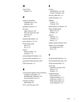
AC adapter connector, 1-2 removal, 4-3 audio card removal, 4-64 jacks location, 1-3 thermal shield removal, 4-64 computer exploded view, 4-10 features, 1-1 illustrated, 1-2 power, 1-5 technical specifications, 1-8 connectors location, 1-3 base assembly exploded view, 4-14 battery location, 1-2 location (options bay), 1-2 removal, 4-4, 4-8 battery charge gauge, 1-4 beep codes during boot routine, 3-1 list of, 3-2 bezel front removal, 4-38 boot routine observing when troubleshooting, 2-4 carrier tray removal, 4-41 CD-ROM drive disassembly, 4-29 location (options bay), 1-2 removal, 4-8 combo module location, 4-8 removal, 4-8 DC-DC board removal, 4-56 Diagnostics Menu, 3-5 diskette drive disassembly, 4-30 location (options bay), 1-2 display close/suspend button, 1-2 latch, 1-2 location, 1-2 display assembly 13.1-inch LCD panel removal, 4-39 13.3-inch exploded view, 4-11 14.1-inch exploded view, 4-12 14.1-inch LCD panel removal, 4-42 carrier tray removal, 4-41 front bezel removal, 4-38 LCD bracket removal, 4-41 location, 4-36 removal, 4-37 DVD-ROM drive disassembly, 4-29 eliminating resource conflicts, 2-5 error messages, 3-2, 3-5 Index 1
-
 1
1 -
2
-
3
-
4
-
5
-
6
-
7
-
8
-
9
-
10
-
11
-
12
-
13
-
14
-
15
-
16
-
17
-
18
-
19
-
20
-
21
-
22
-
23
-
24
-
25
-
26
-
27
-
28
-
29
-
30
-
31
-
32
-
33
-
34
-
35
-
36
-
37
-
38
-
39
-
40
-
41
-
42
-
43
-
44
-
45
-
46
-
47
-
48
-
49
-
50
-
51
-
52
-
53
-
54
-
55
-
56
-
57
-
58
-
59
-
60
-
61
-
62
-
63
-
64
-
65
-
66
-
67
-
68
-
69
-
70
-
71
-
72
-
73
-
74
-
75
-
76
-
77
-
78
-
79
-
80
-
81
-
82
-
83
-
84
-
85
-
86
-
87
-
88
-
89
-
90
-
91
-
92
-
93
-
94
-
95
-
 96
96 -
 97
97 -
 98
98 -
 99
99 -
 100
100 -
 101
101 -
 102
102 -
 103
103 -
 104
104
 |
 |