Denon AVR 4806 Owners Manual - Page 11
Display, DENON LINK indicator - 7 channel a v surround receiver
 |
UPC - 081757506465
View all Denon AVR 4806 manuals
Add to My Manuals
Save this manual to your list of manuals |
Page 11 highlights
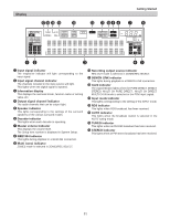
Display !7!6 !5 !4 !3 Getting Started !2 !1 !0o i u y qw e rt q Input signal indicator The respective indicator will light corresponding to the input signal. w Input signal channel indicator The channels included in the input source will light. This lights when the digital signal is inputted. e Information display This displays the surround mode, function name or setting value, etc. r Output signal channel indicator The audio channels that can be output light. t Speaker indicator This lights corresponding to the settings of the surround speakers of the various surround modes. y Decoder indicator This lights when each decoder is operating. u Master volume indicator This displays the volume level. The Setup item number is displayed in System Setup. i IEEE1394 indicator This lights during playback in a IEEE1394 connection. o Multi (zone) indicator ZONE3 mode is selected in ZONE3/REC SELECT. !0 Recording output source indicator REC OUT mode is selected in ZONE3/REC SELECT. !1 DENON LINK indicator This lights during playback in a DENON LINK connection. !2 AL24 indicator The AL24 indicator lights when the PURE DIRECT, DIRECT, STEREO, MULTI CH PURE DIRECT , MULTI CH DIRECT, MULTI CH IN mode is selected in the PCM input signal. !3 Input mode indicator This lights corresponding to the setting of the INPUT mode. !4 RDS indicator This lights when RDS broadcast has been received. !5 AUTO indicator This lights when the broadcast station is selected in the AUTO tuning mode. !6 TUNED indicator This lights when an FM/AM broadcast has been received. !7 STEREO indicator This lights when an FM stereo broadcast has been received. 11
-
 1
1 -
2
-
3
-
4
-
5
-
 6
6 -
 7
7 -
 8
8 -
 9
9 -
 10
10 -
 11
11 -
 12
12 -
 13
13 -
 14
14 -
 15
15 -
 16
16 -
17
-
18
-
19
-
20
-
21
-
22
-
23
-
24
-
25
-
26
-
27
-
28
-
29
-
30
-
31
-
32
-
33
-
34
-
35
-
36
-
37
-
38
-
39
-
40
-
41
-
42
-
43
-
44
-
45
-
46
-
47
-
48
-
49
-
50
-
51
-
52
-
53
-
54
-
55
-
56
-
57
-
58
-
59
-
60
-
61
-
62
-
63
-
64
-
65
-
66
-
67
-
68
-
69
-
70
-
71
-
72
-
73
-
74
-
75
-
76
-
77
-
78
-
79
-
80
-
81
-
82
-
83
-
84
-
85
-
86
-
87
-
88
-
89
-
90
-
91
-
92
-
93
-
94
-
95
-
96
-
97
-
98
-
99
-
100
-
101
-
102
-
103
-
104
-
105
-
106
-
107
-
108
-
109
-
110
-
111
-
112
-
113
-
114
-
115
-
116
-
117
-
118
-
119
-
120
-
121
-
122
-
123
-
124
-
125
-
126
-
127
-
128
-
129
-
130
-
131
-
132
-
133
-
134
-
135
-
136
-
137
-
138
-
139
-
140
-
141
-
142
-
143
-
144
-
145
-
146
-
147
-
148
-
149
-
150
-
151
-
152
-
153
-
154
 |
 |
