Denon AVR 4806 Owners Manual - Page 111
Setting the Digital Out Assignment, User Memory, Digital Out Assign at the Option Setup
 |
UPC - 081757506465
View all Denon AVR 4806 manuals
Add to My Manuals
Save this manual to your list of manuals |
Page 111 highlights
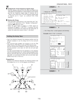
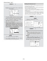
Setting the Digital Out Assignment User Memory Advanced Setup - Part 1 • The optical digital output connectors on the AVR-4806's rear panel (OPTICAL2 to 4 OUT) normally function in association with the ZONE3/REC SELECT mode. With this setting, the OPTICAL 2 OUT connector can be used in association with the ZONE2 SELECT mode. 1 Press the CURSOR D or H button to select the "Digital Out Assign" at the "Option Setup" menu, then press the ENTER button. • Display the "Digital Out Assign" screen. • The currently set settings (system setup, surround parameters, etc.) can be stored in the memory. The stored settings can be called out when needed. 1 Press the CURSOR D or H button to select the "Setup Memory / Lock" at the "Option Setup" menu, then press the ENTER button. • Display the "Setup Memory / Lock" screen. 2 Press the CURSOR F or G button to select whether to associate the OPTICAL2 OUT connector to the "ZONE3/REC SELECT" or "ZONE2 SELECT" mode. 2 Press the CURSOR D or H button to select the "User Memory", then press the ENTER button. • Switch to the "User Memory" screen. 3 Press the ENTER button to enter the setting. • The "Option Setup" menu reappears. 3 Press the CURSOR F button to select the "Yes". • About 30 seconds are required for the settings to be stored in the memory. Once the settings are stored in the memory, "Load" is displayed and the settings can be loaded. 4 Press the CURSOR D or H button to select the "Exit", then press the ENTER button. • Return to the "Setup Memory / Lock" screen. 111
-
 1
1 -
2
-
3
-
4
-
5
-
6
-
7
-
8
-
9
-
10
-
11
-
12
-
13
-
14
-
15
-
16
-
17
-
18
-
19
-
20
-
21
-
22
-
23
-
24
-
25
-
26
-
27
-
28
-
29
-
30
-
31
-
32
-
33
-
34
-
35
-
36
-
37
-
38
-
39
-
40
-
41
-
42
-
43
-
44
-
45
-
46
-
47
-
48
-
49
-
50
-
51
-
52
-
53
-
54
-
55
-
56
-
57
-
58
-
59
-
60
-
61
-
62
-
63
-
64
-
65
-
66
-
67
-
68
-
69
-
70
-
71
-
72
-
73
-
74
-
75
-
76
-
77
-
78
-
79
-
80
-
81
-
82
-
83
-
84
-
85
-
86
-
87
-
88
-
89
-
90
-
91
-
92
-
93
-
94
-
95
-
96
-
97
-
98
-
99
-
100
-
101
-
102
-
103
-
104
-
105
-
 106
106 -
 107
107 -
 108
108 -
 109
109 -
 110
110 -
 111
111 -
 112
112 -
 113
113 -
 114
114 -
 115
115 -
 116
116 -
117
-
118
-
119
-
120
-
121
-
122
-
123
-
124
-
125
-
126
-
127
-
128
-
129
-
130
-
131
-
132
-
133
-
134
-
135
-
136
-
137
-
138
-
139
-
140
-
141
-
142
-
143
-
144
-
145
-
146
-
147
-
148
-
149
-
150
-
151
-
152
-
153
-
154
 |
 |
