HP 6125G HP 6125G & 6125G/XG Blade Switches Layer 3 - IP Services Comm - Page 163
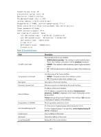
Table 38, Command output, Encapsulation is TUNNEL
 |
View all HP 6125G manuals
Add to My Manuals
Save this manual to your list of manuals |
Page 163 highlights
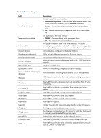
Tunnel0 current state: UP Line protocol current state: UP Description: Tunnel0 Interface The Maximum Transmit Unit is 1476 Internet Address is 58.0.0.1/24 Primary Encapsulation is TUNNEL, service-loopback-group ID is 1. Tunnel source 20.0.0.2 (Vlan-interface2000), destination 20.0.0.1 Tunnel bandwidth 64 (kbps) Tunnel protocol/transport IP/IP Last clearing of counters: Never Last 300 seconds input: 0 bytes/sec, 0 packets/sec Last 300 seconds output: 28 bytes/sec, 0 packets/sec 1847 packets input, 136451 bytes 0 input error 5572 packets output, 428860 bytes 0 output error Table 38 Command output Field Tunnel0 current state Line protocol current state Description Maximum Transmit Unit Internet Address Encapsulation is TUNNEL service-loopback-group ID Tunnel source destination Tunnel bandwidth Description Physical state of the tunnel interface: • DOWN (Administratively)-The interface is administratively down. That is, the interface is shut down with the shutdown command. • DOWN-The interface is administratively up but its physical state is down. • UP-Both the administrative and physical states of the interface are up. Link layer state of the tunnel interface: • DOWN-The protocol state of the interface is down. • UP-The protocol state of the interface is up. Description of the tunnel interface. Maximum transmit unit allowed on the tunnel interface. IP address of the tunnel interface. If no IP address is assigned to the interface, Internet protocol processing : disabled is displayed, which means that packets cannot be processed. Primary indicates the primary IP address of the interface. Sub indicates a secondary IP address of the interface. The encapsulation protocol is tunnel. ID of the service loopback group referenced by the tunnel. If service loopback group is not specified, service-loopback-group ID not set is displayed. Source address of the tunnel. Destination address of the tunnel. Bandwidth of the tunnel interface. 156
-
 1
1 -
2
-
3
-
4
-
5
-
6
-
7
-
8
-
9
-
10
-
11
-
12
-
13
-
14
-
15
-
16
-
17
-
18
-
19
-
20
-
21
-
22
-
23
-
24
-
25
-
26
-
27
-
28
-
29
-
30
-
31
-
32
-
33
-
34
-
35
-
36
-
37
-
38
-
39
-
40
-
41
-
42
-
43
-
44
-
45
-
46
-
47
-
48
-
49
-
50
-
51
-
52
-
53
-
54
-
55
-
56
-
57
-
58
-
59
-
60
-
61
-
62
-
63
-
64
-
65
-
66
-
67
-
68
-
69
-
70
-
71
-
72
-
73
-
74
-
75
-
76
-
77
-
78
-
79
-
80
-
81
-
82
-
83
-
84
-
85
-
86
-
87
-
88
-
89
-
90
-
91
-
92
-
93
-
94
-
95
-
96
-
97
-
98
-
99
-
100
-
101
-
102
-
103
-
104
-
105
-
106
-
107
-
108
-
109
-
110
-
111
-
112
-
113
-
114
-
115
-
116
-
117
-
118
-
119
-
120
-
121
-
122
-
123
-
124
-
125
-
126
-
127
-
128
-
129
-
130
-
131
-
132
-
133
-
134
-
135
-
136
-
137
-
138
-
139
-
140
-
141
-
142
-
143
-
144
-
145
-
146
-
147
-
148
-
149
-
150
-
151
-
152
-
153
-
154
-
155
-
156
-
157
-
 158
158 -
 159
159 -
 160
160 -
 161
161 -
 162
162 -
 163
163 -
 164
164 -
 165
165 -
 166
166 -
 167
167 -
 168
168 -
169
-
170
-
171
-
172
-
173
-
174
-
175
-
176
-
177
-
178
-
179
-
180
-
181
 |
 |