HP ProLiant DL288 HP ProLiant DL288 G6 Server Maintenance and Service Guide - Page 100
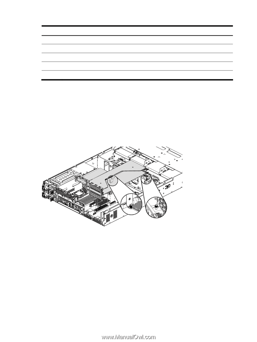
PIC PROG connector, HDD 13 connector, Power connector
 |
View all HP ProLiant DL288 manuals
Add to My Manuals
Save this manual to your list of manuals |
Page 100 highlights
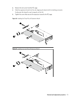
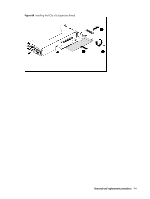
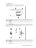
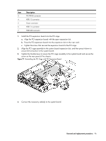
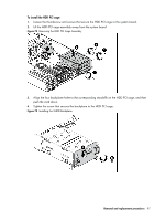
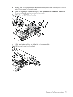
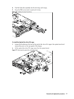
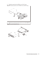
Item 3 4 5 6 7 Description PIC PROG connector HDD 13 connector Power connector HDD 14 connector HDD LED connector 1. Install the PCI expansion board into the PCI cage. a. Align the PCI expansion board with the open expansion slot. b. Press the PCI expansion board into the expansion slot on the riser card. c. Tighten the screw that secures the expansion board to the PCI cage. 2. Align the PCI cage assembly to the system board expansion slot, and then press it down to ensure full connection to the system board. 3. Tighten the thumbscrews to secure the PCI cage assembly to the system board and secure the screw on the rear panel of the chassis. Figure 71 Reinstalling the PCI Cage with PCI Expansion Board 4. Connect the necessary cable(s) to the system board. Removal and replacement procedures 96
-
 1
1 -
2
-
3
-
4
-
5
-
6
-
7
-
8
-
9
-
10
-
11
-
12
-
13
-
14
-
15
-
16
-
17
-
18
-
19
-
20
-
21
-
22
-
23
-
24
-
25
-
26
-
27
-
28
-
29
-
30
-
31
-
32
-
33
-
34
-
35
-
36
-
37
-
38
-
39
-
40
-
41
-
42
-
43
-
44
-
45
-
46
-
47
-
48
-
49
-
50
-
51
-
52
-
53
-
54
-
55
-
56
-
57
-
58
-
59
-
60
-
61
-
62
-
63
-
64
-
65
-
66
-
67
-
68
-
69
-
70
-
71
-
72
-
73
-
74
-
75
-
76
-
77
-
78
-
79
-
80
-
81
-
82
-
83
-
84
-
85
-
86
-
87
-
88
-
89
-
90
-
91
-
92
-
93
-
94
-
 95
95 -
 96
96 -
 97
97 -
 98
98 -
 99
99 -
 100
100 -
 101
101 -
 102
102 -
 103
103 -
 104
104 -
 105
105 -
106
-
107
-
108
-
109
-
110
-
111
-
112
-
113
-
114
-
115
-
116
-
117
-
118
-
119
-
120
-
121
-
122
-
123
-
124
-
125
-
126
-
127
-
128
-
129
-
130
-
131
-
132
-
133
-
134
-
135
-
136
-
137
-
138
-
139
-
140
-
141
-
142
-
143
-
144
-
145
-
146
-
147
-
148
-
149
-
150
-
151
-
152
-
153
-
154
-
155
-
156
-
157
-
158
-
159
-
160
-
161
-
162
-
163
 |
 |