HP ProLiant DL288 HP ProLiant DL288 G6 Server Maintenance and Service Guide - Page 107
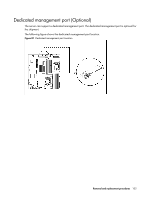
To remove the dedicated management port, Pull the dedicated management port upwards
 |
View all HP ProLiant DL288 manuals
Add to My Manuals
Save this manual to your list of manuals |
Page 107 highlights
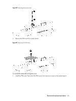
To remove the dedicated management port: 1. Remove the PCI cage assembly out of the chassis. Refer to the "PCI cage" section in this chapter for detailed procedures. 2. Loosen the screw. 3. Pull the dedicated management port upwards, and then remove the dedicated management port from the dedicated management port connector. Figure 82 Removing the dedicated management port 4. Remove the spacer from the system board. Figure 83 Removing the Spacer Removal and replacement procedures 103
-
 1
1 -
2
-
3
-
4
-
5
-
6
-
7
-
8
-
9
-
10
-
11
-
12
-
13
-
14
-
15
-
16
-
17
-
18
-
19
-
20
-
21
-
22
-
23
-
24
-
25
-
26
-
27
-
28
-
29
-
30
-
31
-
32
-
33
-
34
-
35
-
36
-
37
-
38
-
39
-
40
-
41
-
42
-
43
-
44
-
45
-
46
-
47
-
48
-
49
-
50
-
51
-
52
-
53
-
54
-
55
-
56
-
57
-
58
-
59
-
60
-
61
-
62
-
63
-
64
-
65
-
66
-
67
-
68
-
69
-
70
-
71
-
72
-
73
-
74
-
75
-
76
-
77
-
78
-
79
-
80
-
81
-
82
-
83
-
84
-
85
-
86
-
87
-
88
-
89
-
90
-
91
-
92
-
93
-
94
-
95
-
96
-
97
-
98
-
99
-
100
-
101
-
 102
102 -
 103
103 -
 104
104 -
 105
105 -
 106
106 -
 107
107 -
 108
108 -
 109
109 -
 110
110 -
 111
111 -
 112
112 -
113
-
114
-
115
-
116
-
117
-
118
-
119
-
120
-
121
-
122
-
123
-
124
-
125
-
126
-
127
-
128
-
129
-
130
-
131
-
132
-
133
-
134
-
135
-
136
-
137
-
138
-
139
-
140
-
141
-
142
-
143
-
144
-
145
-
146
-
147
-
148
-
149
-
150
-
151
-
152
-
153
-
154
-
155
-
156
-
157
-
158
-
159
-
160
-
161
-
162
-
163
 |
 |
Removal and replacement procedures
103
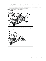
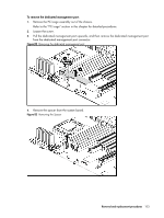
To remove the dedicated management port:
1.
Remove the PCI cage assembly out of the chassis.
Refer to the “PCI cage” section in this chapter for detailed procedures.
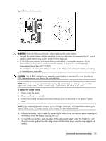
2.
Loosen the screw.
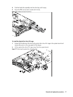
3.
Pull the dedicated management port upwards, and then remove the dedicated management port
from the dedicated management port connector.
Figure 82
Removing the dedicated management port
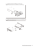
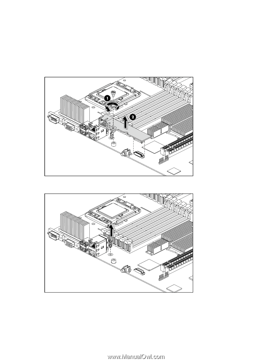
4.
Remove the spacer from the system board.
Figure 83
Removing the Spacer