HP ProLiant DL288 HP ProLiant DL288 G6 Server Maintenance and Service Guide - Page 49
Cable connections, CAUTION, Table 12, Cable, Cable designator
 |
View all HP ProLiant DL288 manuals
Add to My Manuals
Save this manual to your list of manuals |
Page 49 highlights
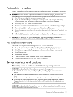
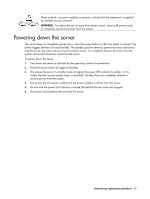
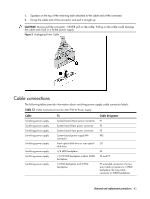
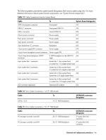
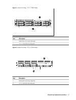
1. Squeeze on the top of the retaining latch attached to the cable end of the connector. 2. Grasp the cable end of the connector and pull it straight up. CAUTION: Always pull the connector-NEVER pull on the cable. Pulling on the cable could damage the cable and result in a failed power supply. Figure 3 Unplugging Power Cable Cable connections The following tables provide information about switching power supply cable connector labels. Table 12 Cable Connections from the 460/750 W Power Supply Cable Switching power supply Switching power supply Switching power supply Switching power supply Switching power supply Switching power supply Switching power supply Switching power supply To System board 24-pin power connector System board 8-pin power connector System board 4-pin power connector System board power supply EFF connector Front optical disk drive or rear optical disk drive 4/8 HDD backplane 12/25 HDD backplane without 2HDD backplane 12 HDD backplane and 2 HDD backplane Cable designator P1 P2 P3 RPS CD P4 P4 and P5 P5 extended connectors, the two short cable connectors to 12HDD backplane, the long cable connector to 2HDD backplane Removal and replacement procedures 45
-
 1
1 -
2
-
3
-
4
-
5
-
6
-
7
-
8
-
9
-
10
-
11
-
12
-
13
-
14
-
15
-
16
-
17
-
18
-
19
-
20
-
21
-
22
-
23
-
24
-
25
-
26
-
27
-
28
-
29
-
30
-
31
-
32
-
33
-
34
-
35
-
36
-
37
-
38
-
39
-
40
-
41
-
42
-
43
-
 44
44 -
 45
45 -
 46
46 -
 47
47 -
 48
48 -
 49
49 -
 50
50 -
 51
51 -
 52
52 -
 53
53 -
 54
54 -
55
-
56
-
57
-
58
-
59
-
60
-
61
-
62
-
63
-
64
-
65
-
66
-
67
-
68
-
69
-
70
-
71
-
72
-
73
-
74
-
75
-
76
-
77
-
78
-
79
-
80
-
81
-
82
-
83
-
84
-
85
-
86
-
87
-
88
-
89
-
90
-
91
-
92
-
93
-
94
-
95
-
96
-
97
-
98
-
99
-
100
-
101
-
102
-
103
-
104
-
105
-
106
-
107
-
108
-
109
-
110
-
111
-
112
-
113
-
114
-
115
-
116
-
117
-
118
-
119
-
120
-
121
-
122
-
123
-
124
-
125
-
126
-
127
-
128
-
129
-
130
-
131
-
132
-
133
-
134
-
135
-
136
-
137
-
138
-
139
-
140
-
141
-
142
-
143
-
144
-
145
-
146
-
147
-
148
-
149
-
150
-
151
-
152
-
153
-
154
-
155
-
156
-
157
-
158
-
159
-
160
-
161
-
162
-
163
 |
 |